Download
1 / 8
80 likes | 189 Vues
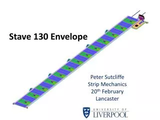
Stave 130 Envelope. Peter Sutcliffe Strip Mechanics 20 th February Lancaster. DC DC Converter-12° Stave angle. DC DC block size shown is 15 long x 6.5 wide x 7mm high. However, current CERN box is 10mm high.

E N D
Stave 130 Envelope Peter Sutcliffe Strip Mechanics 20th February Lancaster
DC DC Converter-12° Stave angle • DC DC block size shown is 15 long x 6.5 wide x 7mm high. However, current CERN box is 10mm high. • ‘Potential’ clashes with opto package and locking point when fixed on the cylinder • New slimmer opto for phase 2 and considering 1 opto per stave located on the ‘top’ side DCDC box mounted on 0.5mm FR4 PCB (Ashley) PCB will be replaced with much thinner Kapton New LightPeak package will solve the opto clash Locking bracket assy 10 mm hightDCDC box clashes with opto and locking point Opto package 7mm high DCDC box shows possible clash with locking bracket
DCDC Continued… • Possible solutions for DCDC converter clash. • Reduce the height to 5mm from 7mm • This would still only give 2mm clearance to the locking point. Is this enough for installation tolerances? • Rotate the stereo modules 180° • This would mean having the power on the stereo tape on the opposite side of the stave i.e. locking bracket side. • Shrinking the PCB board? • Not sure as it may clash with the wire bonds…potential disaster. Power side
Stave positions according to the LoI10° Angle(Hesseyand Hayward)
Potential Clashes • Opto side –I think this will sort itself out i.e. slimmer opto packages or both opto packages on outer stave. • Clash with DCDC to Locking point • Possible solutions: • Place power tracks on the opposite side of tape • Make DCDC a planar coil with thickness less than 4mm • Reduce size of the cylinder mounted locking point • Something else…..…… Worst Case Inner layer with 10° stave angle and 7mm hign DCDC
Details of DCDC InterferenceWith 10°Stave angle (Layer 0) If 7mm DCDC box is used, the clash with the locking bracket is 1.58mm To obtain a clearance of say 2mm, the DCDC box would need to be 3.42mm
Possible solutions… • Possible solutions for DCDC converter clash. • Reduce the height to 3.5mm from 7mm • This would still only give 2mm clearance to the locking point. Is this enough for installation tolerances? • Rotate the stereo modules 180° • This would mean having the power on the stereo tape on the opposite side of the stave i.e. locking bracket side. • Shrinking the PCB board? • Not sure as it may clash with the wire bonds…potential disaster. Power side
Overall 10° End View This view shows a possible solution. Marcel has said that the opto packages could be placed on the ‘outside’ of the stave, which solves the problem on the outer rings. Placing the power on the locking point side for the stereo angle modules would place the DCDC boxes between the locking points. Not sure how feasible this is.