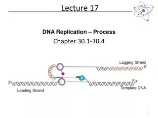
Lecture 17
ENGR-1100 Introduction to Engineering Analysis. Lecture 17. Today Lecture Outline. Trusses analysis- method of section. Stability Criteria. m=2j-3 2j- number of equations to be solved. m- number of members. 3- number of support reaction. m<2j-3. Truss unstable. m>2j-3.

Lecture 17
E N D
Presentation Transcript
Today Lecture Outline Trusses analysis- method of section.
Stability Criteria m=2j-3 2j- number of equations to be solved. m- number of members. 3- number of support reaction m<2j-3 Truss unstable m>2j-3 Statically indeterminate
Method of Joints Separate free-body diagrams for: each member each pin Equilibrium equations for each pin: SF=0 no moment equation
Example 7-16 Determine the forces in members BC, CD, and DF of the truss shown in fig. P7-16
M=9 j=6 M=2j-3 From a free-body diagramfor the complete truss: MA = Ey (8) - 10 (4) - 8 (6) = 0 Ey = 11 kN = 11 kN From a free-body joint E: Solution Fy = TDE sin 30 + 11 = 0 TDE = -22kN = 22 kN (C)
From a free-body joint D: Fy = -TDF cos 30 - 8 cos 30 = 0 TDF = -8 kN = 8 kN (C) Fx = TDE - TCD + 8 sin 30 - TDF sin 30 = (-22) - TCD + 8 sin 30 - (-8) sin 30=0 TCD = -14 kN = 14 kN (C) From a free-body joint C: Fx = -TBC cos 30 + TCD cos 30 = - TBC cos 30 + (-14.00) cos 30 = 0 TBC = -14 kN = 14 kN (C)
Class Assignment: Exercise set 7-46 please submit to TA at the end of the lecture Determine the forces in members BC, BF, and EF of the truss shown in Fig. P7-46 using the joint method. Answer: TBF= 3.75 kN (T) TBC= 2.25 kN (T) TEF= 4.5 kN (C)
Example 7-45 Determine the in members CD, CF, and FG of the bridge shown in Fig. P7-45 using the method of sections.
y x Solution M=11 j=7 M=2j-3 From a free-body diagramfor the complete truss: MA = Ey (45) - 10 (15) - 20 (30) = 0 Ey = 16.699 kip 16.67 kip
y x From a free-body diagram of the part of the truss to the right of member CG: ME = -TCF sin 60 (15) + 20 (15)= 0 TCF = 23.09 kip 23.1 kip (T) MF =TCD (15 sin 30) + 16.667 (15) = 0 TCD = -33.33 kip 33.3 kip (C) MC = -TFG (22.5 tan 30) - 20(7.5) +16.667(22.5) = 0 TFG = 17.321 kip 17.32 kip (T)
Class Assignment: Exercise set P7-46 please submit to TA at the end of the lecture Determine the in members BC, BF, and EF of the truss shown in Fig. P7-46 using the method sections. Answer: TBF= 3.75 kN (T) TBC= 2.25 kN (T) TEF= 4.5 kN (C)
Free body diagram on joint C y FBC x FCD FCD=0 FBC=0 SFx=0 Member BC and DC are zero force members Zero Force Members SFy=0
Free body diagram on joint B y y FCB FAB x x FBD FBD=0 Free body diagram on joint D FDC FAD FAD=0 FED SFy=0
Class Assignment: Exercise set 7-35 to 7-38 please submit to TA at the end of the lecture Identify the zero-force members present when the trusses shown in the following problems are subjected to the loadings indicated.