Download
1 / 64
650 likes | 848 Vues
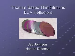
Optical Constants of Sputtered Thoria Thin Films Useful in EUV Optics from IR to EUV. David D. Allred Brigham Young University. EUV Lithography. EUV Astronomy. Soft X-ray Microscopes. The Earth’s magnetosphere in the EUV. Our Goal – EUV Applications.

E N D
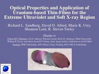
Optical Constants of Sputtered Thoria Thin Films Useful in EUV Optics from IR to EUV David D. Allred Brigham Young University
EUV Lithography EUV Astronomy Soft X-ray Microscopes The Earth’s magnetosphere in the EUV Our Goal – EUV Applications • Extreme Ultraviolet Optics has many applications. • These Include: • EUV Lithography • EUV Astronomy= image mission • Soft X-ray Microscopes • A Better Understanding ofEUV Optics & Materials for EUV applications is needed.
William R. Evans: senior (honors) thesis: Spectroscopic ellipsometry 1- 6.5 eV Niki F. Brimhall: senior (honors) thesis: EUV optical constants of Thoria (also Guillermo Acosta & Jed E. Johnson. ) Sarah C. Barton 10.2 eV reflectance (Monarch) R.S. Turley: most everything spectroscopic >10 eV. Michael Clemens: AFM XPS Amy B. Grigg and The BYU EUV Thin Film Optics Group, past and present who went to ALS : Jacque Jackson, Elise Martin, Lis Strein, Joseph Muhlestein Dr. Thomas Tiwald: JA Woollam Co: interpretation & extending range of Spec. Ellips. To IR and 9.5 eV Matt Linford’s Group (Chem.) Participants
Financial + Other Assistance • BYU Department of Physics and Astronomy shop & electronics • BYU Office of Research and Creative Activities • Rocky Mountain NASA Space Grant Consortium • V. Dean and Alice J. Allred, Marathon Oil Company • ALS time (DOE) and help @ beamline 6.3.2: Eric Gullikson, Andy Aquila
Outline • XUV Optics • Applications -Production • Review of Optics for EUV/ x-rays (E>15 eV) • Why Actinides in EUV? Why Oxides? • besides ML there are low-angle front surface mirrors • Optical constants from R and T • Measuring XUV OC with Reflectance & Transmission on “Absolute” X-ray diodes • Real Surfaces: Characterizing & Improving them. • Spectroscopic Ellipsometry 1- 6.5 eV: • Thoria has some leftover problems in solid state. • Index and band gap.
Extreme Ultraviolet Optics—What is our end goal? Multilayer Mirrors Astronomy Lithography Microscopy
Optics like n-IR, visible, & n-UV? • How to manipulate light? • Lens? Prisms? Mirrors? Diff Gratings? ML interference coatings? • We need to have optical constants; • How to get in EUV? • Kramers-Kronig equations n () k () • Variable angle of reflection measurements, • Real samples aren’t good enough. Roughness
Absorption and Refraction • Optical properties characterized by index of refraction n • Visible • n real (often >>1) • n >0 (total internal reflection) • XUV and X-Rays • n complex; n=1-δ+iβ • Re(n) < 1 (but not by much)
Complex Index of Refraction • Real n • Complex n=1-δ+iβ • β = k
Multilayer Mirrors • Problems • Need constructive interference • Absorption in layers
U/Si ML coating for EUV instrument • Picture (41 eV) is from EUV imager on the IMAGE Spacecraft. He (II) in magnetosphere • This was student powered project 1997-98 • Designed: needed 7 degree width off normal, 7.5 layer U/Si ML with U Oxide cap- peak R 25% • Coated & • Tested • Launched 2000 March 25
EUV Multilayer Optics 101 High reflectivity multilayer coatings require: • Refractive index (n = 1-δ+iβ) contrast at the interfaces: for most materials, these optical constants are not well known in this region. • Minimal absorption in the low-Z material • Interfaces which are chemically stable with time • Minimal interdiffusion at the interfaces • Thermal stability during illumination • Chemically stable vacuum interface Even with the very best designs, multilayer mirrors have only achieved a reflectivity of around 70% in the EUV.
The solution? Research of new materials with these properties Uranium: • Highly reflective in the region from 124-248 eV [1] • Not chemically stable with time Uranium Oxide: • Highly reflective in the region from 124-248 eV [1] • Not chemically stable with time Thorium: • Highly reflective in the region from 138-177 eV [2] • Not chemically stable with time, tho better than U. [1] RL Sandberg, DD Allred, JE Johnson, RS Turley, " A Comparison of Uranium Oxide and Nickel as Single-layer Reflectors", Proceedings of the SPIE, Volume 5193, pp. 191-203 (2004). [2] J. Johnson, D. Allred, R.S. Turley, W. Evans, R. Sandburg, “Thorium-based thin films as highly reflective mirrors in the EUV”, Materials Research Society Symposium Proceedings 893, 207-213, 2006.
Solutions • n=1-δ+iβ • Find materials with big δ and small β • Good candidates: High Density, High -Z materials like U. But Oxidation occurs. • Th as ThO2 has entrée.
How to Get OC from Data • Measure reflectance and/or transmission • Multiple wavelengths • Multiple angles • Fit data to a theoretical Model • film thicknesses • optical parameters • But reflectance is sensitive to surface- inhomogeneities roughness; oxidation
Transmissionk? • T = (Corrections) exp (-αd); • Corrections are due to R and can be small • At normal incidence R goes as [2 + β2]/4 • If film is close to detector scattering due to roughness etc. is less important. • But how to get an even, thin film? • A very thin membrane?
Measurements of reflectance and transmittance ~20 nm reactively sputtered ThO2 on a polyimide membrane (~100 nm, Moxtek) and a naturally oxidized silicon substrate.
Better procedures for fitting • Take several measurements—use each measurement to constrain those parameters to which it is most sensitive
A major problem with our first try • Measurements of thorium dioxide deposited on polyimide films gave unreliable data. Reflectances measured with different filter sets differed by as much as 32% of total reflectance. Absolute transmission measurements were uncertain by as much as 19%.
Optical Constants Even though our absolute transmission was uncertain to this degree, the energy of the incident light was known to 0.012%, and so even if the exact values of delta and beta are off, the edges won’t be.
A second method that worked • Thorium dioxide deposited on AXUV-100 silicon photodiodes (IRD).
Verification and a surprise • In delta: a peak shift to lower energies by 3 eV from 92.8 eV
Verification and a surprise • In beta: absorption edge shifts to lower energies from those of thorium by 4 eV from 105.6 eV and 2 eV from 91.5 eV
Summary and Conclusions • We report the optical constants of ThO2 from 50- 108 eV • We have used constraining techniques to fit optical constants including fitting film thickness using interference fringes in highly transmissive areas of the spectrum and fitting reflectance and transmittance data simultaneously • In delta we observed a peak shift to lower energies from that of thorium by 3 eV from 92.8 eV • In beta we observed absorption edge shifts to lower energies from those of thorium by 4 eV from 105.6 eV and 2 eV from 91.5 eV
The problem is waviness of substrate. Sample on Si does fine.
The Solution: Deposit the film on the detector • Uspenskii, Sealy and Korde showed that you could deposit a film sample directly onto an AXUV100 silicon photodiode (IRD) and determine the films transmission ( by ) from the ratio of the signals from various coated diodes with identical capping layers. • JOSA 21(2) 298-305 (2004).
Our group’s 1st approach • Measure the reflectance of the coated diode at the same time I am measuring the transmission. And • Measure both as a function of angle. And • Get the film thickness from the (R and T data) to check ellipsometry of witness.
Fitting T() to get dead layer thickness (6-7nm) on bare AXUV diode @=13.5nm
Focusing on the high reflectance & transmission had a problem
Comments • Either T or R have n and k data, but • Transmission has very little n data when δ is small (the EUV). • Reflection n, k and when interference fringes are seen, and • It has thickness (z) data. What follows shows how we confirmed thickness for air-oxidized Sc sputter-coated AXUV diodes.
Our recent group’s approach • Measure the reflectance of the coated diode at the same time I am measuring the transmission. And • Measure both as a function of angle. And • Get the film thickness from the (R) interference fringes (@ high angles).
The complete set of R data (6<θ<200) zfit =28.1 nm @ =4.7 nm
Reflectance and transmittance of a ThO2-coated diode at 15 nm fitted simultaneously to obtain n&k • Green (blue) shows reflectance (transmission) as a function of grazing angle ()* • Noted the interference fringes at higher angles in R. * is always from grazing incidence
R &T of a ThO2-coated diode at 12.6 nm fitted simultaneously to obtain optical constants. • The fits were not very good at wavelengths where the transmission was lower than 4%. • All of these fits were trying to make the fit of transmission narrower than the data was.
Thin films of scandium oxide, 15-30 nm thick, were deposited on silicon photodiodes by Sputtering Sc from a target & letting it air oxidize OR reactively sputtering scandium in an oxygen environment. Similar thing was done with Thorium to make Thoria R and T Measured using synchrotron radiation at the als (Beamline 6.3.2), at LBNL over wavelengths from 2.5-40 nm at variable angles, were taken simultaneously. “Intermediate Conclusions”
ThO2 • A number of studies by our group have shown that thorium and thorium oxide (ThO2) have great potential as highly reflective coatings in the EUV. • In certain regions, ThO2 may be the best monolayer reflector that has yet been studied.
XUV Optics Production • Sputtering or Evaporation
Biased Sputtering • Our films were deposited by biased RF Magnetron Sputtering. • ThO2 was reactively sputtered off of a depleted thorium target with oxygen introduced in the chamber. • Chamber sputtering pressures were about 10-4 torr. • Bias voltages were between 0 and -70 V DC.
Film Characterization • Film composition was measured using x-ray photoelectron spectroscopy. Th % stayed between 60% and 70% with oxygen making up the balance of the composition. Only traces of other elements were detected. • X-ray diffraction was used 1) as a first measurement of film thickness and 2) to measure crystal structure. Orientations (111), (200), (220), and (311) were clearly visible, with other orientations being largely absent.
Spectroscopic Ellipsometry • Optical characteristics were measured using spectroscopic ellipsometry in the visible and near UV. • Ellipsometric data were taken from samples deposited on silicon between 1.2 and 6.5 eV at angles of every degree between 67° and 83°. • Normal incidence transmission data were taken over the same range of energies, from samples deposited on quartz slides.
Data Fitting • The data were modeled using the J. A. Woollam ellipsometry software. • n is modeled parametrically using a Sellmeier model which fits ε1 using poles in the complex plane. • The Sellmeier model by itself doesn’t account for absorption. (i.e. All poles are real.) • k can be added in separately, either by fitting point by point, or by modeling ε2 with parameterized oscillators.