Download
1 / 20
200 likes | 465 Vues
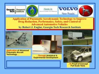
Application of Pneumatic Aerodynamic Technology to Improve Drag Reduction, Performance, Safety, and Control of Advanced Automotive Vehicles by Robert J. Englar, Georgia Tech Research Institute. Application of Advanced Pneumatic Aircraft Technology …. ...Through Analytical &

E N D
Application of Pneumatic Aerodynamic Technology to Improve Drag Reduction, Performance, Safety, and Control of Advanced Automotive Vehicles by Robert J. Englar, Georgia Tech Research Institute Application of Advanced Pneumatic Aircraft Technology…. ...Through Analytical & Experimental Development ... ..To Proof-of-Concept Full-Scale Tests
• Introduction: Pneumatic Heavy Vehicle Aerodynamic Technology • Pneumatic Heavy Vehicles (PHV)….Multi-Purpose Aero Devices for: Force & Moment Reductions or Augmentations Drag Reduction (Fuel Efficiency) or Drag Increase (Aero Braking) Increased Stability (Directional & Lateral) Improved Safety of Operation Reduced Spray Turbulence & Hydroplaning No-Moving-Part Integrated System Pneumatic Cooling System • Wind-tunnel Investigations &Confirmations • Initial Full-Scale Tuning Tests at Volvo Trucks • SAE Type II Fuel Economy Tests at TRC • Other Applications: Pneumatic SUV & Aero Heat Exchanger • Conclusions: Summary of Wind-Tunnel & Full-Scale Results Outline of Presentation
Circulation Control Concept on Aircraft Navy A-6/CCW Flight Test Aircraft Blowing on Front of Trailer and/or All 4 Trailing Edges Basics of Circulation Control Pneumatic Aerodynamics and Application to Heavy Vehicles
Pneumatic Aero Development at GTRI Showed 50%(or more) Drag Reduction, Force & Moment Augmentation from Blown Configurations, andDrag Increase for Aero Braking if Desired -23.9% -10.2% DCD due to Blowing -26.8% 4 Blown Slots & Jet Turning on Rear Doors of Wind-Tunnel Model
GTRI Extended Cm Tests Showed State-of-the-Art Drag Reduction!! 1999 Corvette Coupe 1999 Ferrari 550 2001 Honda Insight
Directional Control Capability Provided by Blowing of Left Side Slot Only (Similar Effects on Drag) Yaw Nose Left, Blow HERE Additional Gain from Side Blowing = Reduced CDdue to Yaw
Tufts Slots, 4 total, one per side Static Jet Turning Displayed During Full-scale Run-up Testing Setting Slot Heights and Confirming Jet Turning at Low Blowing Rate on Aft Door of Trailer Right Rear Corner, looking up-- Tufts Show Jet Turning to Left: 90° on Side and 30° on Top
On-the-Road Operation: Jet Turning Entraining the Freestream Flowfield and Reducing Vehicle Drag Rear View with Jets Blowing Close-up of Tufts Showing Jet Turning
Pneumatic Heavy Vehicle (PHV) Test Rig on Track for Fuel Test 1 at TRC, 75 mph with Blowing SAE Fuel Test I Results: 5-6% Fuel Economy Increase ~ 10-12% CD Reduction New Wind Tunnel Tests were Conducted to Identify Initial Problem areas, then Fuel Test II was conducted in Sept. 2004
Tests of this new model completed at GTRI; Showed 31% Lower CD than Stock Truck Airfoil Airfoil Updated PHV Blown Wind-tunnel Model to Resemble TRC Test Rig,With New Tractor, New Top Strut Mount, New TE Geometry Air Supply Line Faired Mounting Strut New Blown Trailing-edge Geometry, 53’ Trailer Generic Conventional Model (GCM) Cab (DOE Team design) Optional Gap Side Plates High Floor, Wheels & Undercarriage Details, No Fairing
Second SAE Type II Fuel Economy Test at TRC Revised Pneumatic Heavy Vehicle Test Rig Baseline Stock Heavy Vehicle Control Truck
SAE Fuel Economy Results at TRC, Test 2 - Improvements due to Blowing and Aft Trailer Geometry
Fuel Usage in the US (look at SUVs), and One Possible Fix:Increase Fuel Efficiency of SUVs DOE Fuel Usage Data, 109 gallons/year Blown SUV in Lockheed Tunnel
Full-Scale Tunnel Tests of Unblown SUV to Locate Flow Separation for Blowing Slot Location of Pneumatic SUV Smoke Flow over Unblown SUV , Testing in Lockheed 16’ x 23’ Low Speed Wind Tunnel, Marietta GA Separated Flow over Aft Door of SUV
Pneumatic Capabilities of Blown SUV Confirmed in WT Test;Blowing Configs far from Optimized Drag Reduction or Aero Braking~ Functions Interchangeable: Which Slot Blown Directional Stability, No Moving Parts
Blowing Demonstrated on Full-Scale PHV Tests at TRC, Confirming Drag Reduction, but less than from Tunnel Tests; Reasons Now Identified • 15-16% Fuel Efficiency Improvement is PossibleBased on 31% ModelCD Reduction • ~TRC Track Test Results Show 11-12% Fuel Economy Increase due to Blowing • and Aft Geometry (not including blower fuel; better blower or pump would help) • Pneumatic Yaw Stability, Side-Wind CD Reduction,and Aero Braking Capabilities • (Safety of Operation) are Confirmed, Model & Full-scale Testing • Pneumatic Full-scale Tunnel Tests Showed Similar Blown Capabilities for SUVs • • Let’s get this on Production Trucks & Fleets!! (12%FEI=2.4 Billion gals of diesel/yr) • GTRI PATENTED • CONCEPTS CONCLUSIONS: Pneumatic Aerodynamic Concepts Now Demonstrated Full-Scale on PHV and PSUV
TheVertical Mid Base The Effects of Blowing on Increasing Base Pressure for CD Reduction Vertical Mid Base Horizontal Mid Base
Flow Visualization of Blowing Jets Tuft Showing Flow Uniformity at Diffuser Center Combined Jet Strength and Wake Contraction (see Shirt)
Blowing Efficiency & Drag/Thrust Increment Due to Blowing Slot Position, shown as Fraction/Multiple of Blowing Momentum Input It’s possible to get back 5.5 times the Cm input as a CD Reduction…. OR 2 times the Cm input as Aero Braking increase