Download
1 / 64
810 likes | 1.31k Vues
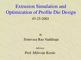
Extrusion Simulation and Optimization of Profile Die Design. By Srinivasa Rao Vaddiraju. 03-25-2003. Advisor Prof. Milivoje Kostic. Polymer pellets. Dopants. Dryer. Feeding. Hopper. Breaker plate. Cooling. Haul-off. Die. Cutter. Calibrator. Extruder. Measurement. Introduction.

E N D
Extrusion Simulation and Optimization of Profile Die Design By Srinivasa Rao Vaddiraju 03-25-2003 Advisor Prof. Milivoje Kostic
Polymer pellets Dopants Dryer Feeding Hopper Breaker plate Cooling Haul-off Die Cutter Calibrator Extruder Measurement Introduction Extrusion describes the process by which a polymer melt is pushed across a metal die, which continuously shapes the melt into the desired form. Gear pump A Schematic of Profile Extrusion Line at FNAL
Quality factors Extrudate swell rearrangement of the velocity profile as the polymer leaves the die Draw down Cooling Insufficient mixing in the extruder Uneven die body temperatures and raw material variations Non-uniform viscosity in the die Non-uniform swelling Non-uniform draw down
An attempt to develop a possible strategy for effective die design in profile extrusion Investigate the die swell behavior of the polymer and to predict the optimum die profile-shape and dimensions, including the pin(s) profile, to obtain the required dimensions and quality of the extrudate. Investigate the swell phenomenon and mass flow balance affected by different parameters like die lengths, flow rates, exponent in viscosity function etc. Simulate the flow and heat transfer of molten polymer inside the die and in the free-flow region after the die exit, and compute pressure, temperature, velocity, stress and strain rate distributions over the entire simulation domain. Investigate and understand over-all polymer extrusion process, and integrate the simulation results with the experimental data, to optimize the die design and ultimately to achieve better quality and dimensions of the extrudate. Prepare the complete design of dies, including blue prints. Objectives
An attempt to develop a possible strategy for effective die design in profile extrusion Investigate the die swell behavior of the polymer and to predict the optimum die profile-shape and dimensions, including the pin(s) profile, to obtain the required dimensions and quality of the extrudate. Investigate the swell phenomenon and mass flow balance affected by different parameters like die lengths, flow rates, exponent in viscosity function etc. Simulate the flow and heat transfer of molten polymer inside the die and in the free-flow region after the die exit, and compute pressure, temperature, velocity, stress and strain rate distributions over the entire simulation domain. Investigate and understand over-all polymer extrusion process, and integrate the simulation results with the experimental data, to optimize the die design and ultimately to achieve better quality and dimensions of the extrudate. Prepare the complete design of dies, including blue prints. Objectives
An attempt to develop a possible strategy for effective die design in profile extrusion Investigate the die swell behavior of the polymer and to predict the optimum die profile-shape and dimensions, including the pin(s) profile, to obtain the required dimensions and quality of the extrudate. Investigate the swell phenomenon and mass flow balance affected by different parameters like die lengths, flow rates, exponent in viscosity function etc. Simulate the flow and heat transfer of molten polymer inside the die and in the free-flow region after the die exit, and compute pressure, temperature, velocity, stress and strain rate distributions over the entire simulation domain. Investigate and understand over-all polymer extrusion process, and integrate the simulation results with the experimental data, to optimize the die design and ultimately to achieve better quality and dimensions of the extrudate. Prepare the complete design of dies, including blue prints. Objectives
An attempt to develop a possible strategy for effective die design in profile extrusion Investigate the die swell behavior of the polymer and to predict the optimum die profile-shape and dimensions, including the pin(s) profile, to obtain the required dimensions and quality of the extrudate. Investigate the swell phenomenon and mass flow balance affected by different parameters like die lengths, flow rates, exponent in viscosity function etc. Simulate the flow and heat transfer of molten polymer inside the die and in the free-flow region after the die exit, and compute pressure, temperature, velocity, stress and strain rate distributions over the entire simulation domain. Investigate and understand over-all polymer extrusion process, and integrate the simulation results with the experimental data, to optimize the die design and ultimately to achieve better quality and dimensions of the extrudate. Prepare the complete design of dies, including blue prints. Objectives
An attempt to develop a possible strategy for effective die design in profile extrusion Investigate the die swell behavior of the polymer and to predict the optimum die profile-shape and dimensions, including the pin(s) profile, to obtain the required dimensions and quality of the extrudate. Investigate the swell phenomenon and mass flow balance affected by different parameters like die lengths, flow rates, exponent in viscosity function etc. Simulate the flow and heat transfer of molten polymer inside the die and in the free-flow region after the die exit, and compute pressure, temperature, velocity, stress and strain rate distributions over the entire simulation domain. Investigate and understand over-all polymer extrusion process, and integrate the simulation results with the experimental data, to optimize the die design and ultimately to achieve better quality and dimensions of the extrudate. Prepare the complete design of dies, including blue prints. Objectives
An attempt to develop a possible strategy for effective die design in profile extrusion Investigate the die swell behavior of the polymer and to predict the optimum die profile-shape and dimensions, including the pin(s) profile, to obtain the required dimensions and quality of the extrudate. Investigate the swell phenomenon and mass flow balance affected by different parameters like die lengths, flow rates, exponent in viscosity function etc. Simulate the flow and heat transfer of molten polymer inside the die and in the free-flow region after the die exit, and compute pressure, temperature, velocity, stress and strain rate distributions over the entire simulation domain. Investigate and understand over-all polymer extrusion process, and integrate the simulation results with the experimental data, to optimize the die design and ultimately to achieve better quality and dimensions of the extrudate. Prepare the complete design of dies, including blue prints. Objectives
An attempt to develop a possible strategy for effective die design in profile extrusion Investigate the die swell behavior of the polymer and to predict the optimum die profile-shape and dimensions, including the pin(s) profile, to obtain the required dimensions and quality of the extrudate. Investigate the swell phenomenon and mass flow balance affected by different parameters like die lengths, flow rates, exponent in viscosity function etc. Simulate the flow and heat transfer of molten polymer inside the die and in the free-flow region after the die exit, and compute pressure, temperature, velocity, stress and strain rate distributions over the entire simulation domain. Investigate and understand over-all polymer extrusion process, and integrate the simulation results with the experimental data, to optimize the die design and ultimately to achieve better quality and dimensions of the extrudate. Prepare the complete design of dies, including blue prints. Objectives
Design Methodology Using Finite Element based CFD code Polyflow Using the method of Inverse Extrusion To fully understand the extrusion processes and the influence of various parameters on the quality of the final product. Integrate the simulation results and the experimental data to obtain more precise extrudate shape.
Literature Review The text book “Dynamics of Polymeric Liquids” by R.B.Bird gives a detailed overview of non-Newtonian fluid dynamics, which is important to understand the flow of polymers. The text book “Extrusion Dies” by Walter Michaeli gives an extensive representation of extrusion processes and guidelines for the design of dies. The text book “Plastics Extrusion Technology Handbook” by Levis gives a clear representation of the rheology of materials and the technology of extrusion processes. Woei-Shyong Lee and Sherry Hsueh-Yu Ho have investigated the die swell behavior of a polymer melt using finite element method and simulated flow of Newtonian fluid and designed a profile extrusion die with a geometry of a quarter ring profile Louis G. Reifschneider has designed a coat hanger extrusion die using a parametric based three-dimensional polymer flow simulation algorithm, where the shape of the manifold and land are modified to minimize the velocity variation across the die exit. W.A. Gifford has demonstrated through an actual example how the efficient use of 3-D CFD algorithms and automatic finite element mesh generators can be used to eliminate much of the “cut and try” from profile die design.
Continuity Equation Governing Equations Momentum Equation Where, P is the pressure, τ is the extra stress tensor, v is the velocity.
Energy Equation the accumulation term, the convection term, the conduction term, the dissipation term, Where, Cv is the specific heat capacity of the material, T is the temperature, ρ is the density, k is the thermal conductivity.
Die Design • The ‘art of die design’ is to predict ‘properly irregular’ die shape (with minimum number of trials) which will allow melt flow to reshape and solidify into desired (regular) extrudate profile. • The correct geometry of the die cannot be completely determined from engineering calculations. • Numerical methods
POLYFLOW • Finite-element CFD code • Predict three-dimensional free surfaces • Inverse extrusion capability • Strong non-linearities • Evolution procedure
Flowchart for numerical simulation using Polyflow 1. Draw the geometry in Pro-E (or) other CAD software and export to GAMBIT 2. Draw the geometry in GAMBIT (or) import from other CAD software and mesh it. Modify the mesh 3. Specify Polymer properties in Polydata 4. Specify boundary conditions in Polydata Change the remeshing techniques and/or solver methods 5. Specify remeshing technique and solver method in Polydata 6. Specify the evolution parameters in Polydata Modify the evolution parameters 7. Polyflow solves the conservation equations using the specified data and boundary conditions 8.Is the solution converged? No Yes Stop
General Assumptions The flow is steady and incompressible Body forces and Inertia effects are negligible in comparison with viscous and pressure forces. Specific heat at constant pressure, Cp, and thermal conductivity, k, are constant
Boundary Conditions Inlet: Fully developed inlet velocity corresponding to actual mass flow rate of 50 kg/hr and uniform inlet temperature (473 K or 200 C). Die, spider and pin walls: No slip at the die walls (Vn =Vs = 0; normal and streamline velocities, respectively), and uniform die wall temperature 473 K. Symmetry planes: Shear stress Fs = 0, normal velocity Vn = 0 and normal heat flux qn =0. Free surface: Zero pressure and traction/shear at boundary (Fn = 0, Fs = 0, and Vn =0), and convection heat transfer from the free surface to surrounding room- temperature air. Kinematic balance equation on δΩfree Outlet: Normal stress Fn =0, Tangential Velocity Vs = 0, Pressure = 0.0 (reference pressure) and normal heat flux qn =0. All domains: Viscous dissipation was neglected for all flow conditions (after verification).
Boundary Conditions Inlet: Fully developed inlet velocity corresponding to actual mass flow rate of 50 kg/hr and uniform inlet temperature (473 K or 200 C). Die, spider and pin walls: No slip at the die walls (Vn =Vs = 0; normal and streamline velocities, respectively), and uniform die wall temperature 473 K. Symmetry planes: Shear stress Fs = 0, normal velocity Vn = 0 and normal heat flux qn =0. Free surface: Zero pressure and traction/shear at boundary (Fn = 0, Fs = 0, and Vn =0), and convection heat transfer from the free surface to surrounding room- temperature air. Kinematic balance equation on δΩfree Outlet: Normal stress Fn =0, Tangential Velocity Vs = 0, Pressure = 0.0 (reference pressure) and normal heat flux qn =0. All domains: Viscous dissipation was neglected for all flow conditions (after verification).
Boundary Conditions Inlet: Fully developed inlet velocity corresponding to actual mass flow rate of 50 kg/hr and uniform inlet temperature (473 K or 200 C). Die, spider and pin walls: No slip at the die walls (Vn =Vs = 0; normal and streamline velocities, respectively), and uniform die wall temperature 473 K. Symmetry planes: Shear stress Fs = 0, normal velocity Vn = 0 and normal heat flux qn =0. Free surface: Zero pressure and traction/shear at boundary (Fn = 0, Fs = 0, and Vn =0), and convection heat transfer from the free surface to surrounding room- temperature air. Kinematic balance equation on δΩfree Outlet: Normal stress Fn =0, Tangential Velocity Vs = 0, Pressure = 0.0 (reference pressure) and normal heat flux qn =0. All domains: Viscous dissipation was neglected for all flow conditions (after verification).
Boundary Conditions Inlet: Fully developed inlet velocity corresponding to actual mass flow rate of 50 kg/hr and uniform inlet temperature (473 K or 200 C). Die, spider and pin walls: No slip at the die walls (Vn =Vs = 0; normal and streamline velocities, respectively), and uniform die wall temperature 473 K. Symmetry planes: Shear stress Fs = 0, normal velocity Vn = 0 and normal heat flux qn =0. Free surface: Zero pressure and traction/shear at boundary (Fn = 0, Fs = 0, and Vn =0), and convection heat transfer from the free surface to surrounding room- temperature air. Kinematic balance equation on δΩfree Outlet: Normal stress Fn =0, Tangential Velocity Vs = 0, Pressure = 0.0 (reference pressure) and normal heat flux qn =0. All domains: Viscous dissipation was neglected for all flow conditions (after verification).
Boundary Conditions Inlet: Fully developed inlet velocity corresponding to actual mass flow rate of 50 kg/hr and uniform inlet temperature (473 K or 200 C). Die, spider and pin walls: No slip at the die walls (Vn =Vs = 0; normal and streamline velocities, respectively), and uniform die wall temperature 473 K. Symmetry planes: Shear stress Fs = 0, normal velocity Vn = 0 and normal heat flux qn =0. Free surface: Zero pressure and traction/shear at boundary (Fn = 0, Fs = 0, and Vn =0), and convection heat transfer from the free surface to surrounding room-temperature air. Kinematic balance equation on δΩfree Outlet: Normal stress Fn =0, Tangential Velocity Vs = 0, Pressure = 0.0 (reference pressure) and normal heat flux qn =0. All domains: Viscous dissipation was neglected for all flow conditions (after verification).
Boundary Conditions Inlet: Fully developed inlet velocity corresponding to actual mass flow rate of 50 kg/hr and uniform inlet temperature (473 K or 200 C). Die, spider and pin walls: No slip at the die walls (Vn =Vs = 0; normal and streamline velocities, respectively), and uniform die wall temperature 473 K. Symmetry planes: Shear stress Fs = 0, normal velocity Vn = 0 and normal heat flux qn =0. Free surface: Zero pressure and traction/shear at boundary (Fn = 0, Fs = 0, and Vn =0), and convection heat transfer from the free surface to surrounding room- temperature air. Kinematic balance equation on δΩfree Outlet: Normal stress Fn =0, Tangential Velocity Vs = 0, Pressure = 0.0 (reference pressure) and normal heat flux qn =0. All domains: Viscous dissipation was neglected for all flow conditions (after verification).
Boundary Conditions Inlet: Fully developed inlet velocity corresponding to actual mass flow rate of 50 kg/hr and uniform inlet temperature (473 K or 200 C). Die, spider and pin walls: No slip at the die walls (Vn =Vs = 0; normal and streamline velocities, respectively), and uniform die wall temperature 473 K. Symmetry planes: Shear stress Fs = 0, normal velocity Vn = 0 and normal heat flux qn =0. Free surface: Zero pressure and traction/shear at boundary (Fn = 0, Fs = 0, and Vn =0), and convection heat transfer from the free surface to surrounding room- temperature air. Kinematic balance equation on δΩfree Outlet: Normal stress Fn =0, Tangential Velocity Vs = 0, Pressure = 0.0 (reference pressure) and normal heat flux qn =0. All domains: Viscous dissipation was neglected for all flow conditions (after verification).
Styron 663, mixed with Scintillator dopants Material Data Measured by, Datapoint Labs Carreau-Yasuda Law for viscosity data: Zero shear rate viscosity, η0 = 36,580 Pa-s Infinite shear rate viscosity, η∞ = 0 Pa-s Natural time, λ = 0.902 Transition Parameter, a = 0.585 Exponent, n = 0.267 Density, ρ = 1040 Kg/m3 Specific Heat, cp = 1200 J/Kg-K Thermal Conductivity, k = 0.12307 W/m-K Coefficient of thermal expansion, β = 0.5e-5 m/m-K
106 η – Styron 663 ηd– Doped Styron 663 105 180 0C 200 0C 220 0C 104 103 102 10-2 10-1 100 103 102 101 • Styron viscosity data, with and without Scintillator dopants
Profiles Rectangular profile die with one hole Rectangular profile die with ten holes
0.11 1.0 2.0 Rectangular profile die with one hole Required extrudate is a rectangular cross section of 1 cm 2 cm with a circular hole of 1.1 mm diameter at its center ALL DIMENSIONS ARE IN CM
Sensitivity analysis of die swell and inverse extrusion capabilities of Polyflow P3 (x,y) P2 (0,y) P1 (0,y) P5 (x,0) P4 (x,0)
Full domain of the extrusion die Melt flow direction
Section 3 Melt flow direction Section 2 Die lip Section 1 Half domain of the extrusion die
Simulation domain with boundary conditions • . Inlet (Fully Developed Flow) 2. Wall (Vn = 0, Vs = 0) 3. Symmetry (Vn = 0, Fs = 0) • . Free Surface (Fs = 0, Fn = 0, V.n = 0) • . Outlet (Fn = 0, Vs = 0)
Finite element 3-D domain and die-lip mesh Melt flow direction Die Lip 30,872 elements Skewness < 0.33
19 hours and 36 minutes of CPU time • Windows XP • 2.52 GHz Processor • 1 GB RAM
Melt flow direction Die lip Contours of static pressure
Melt flow direction Die lip Contours of velocity magnitude at different iso-surfaces
Melt flow direction Die lip Contours of temperature distribution
Die lip Melt flow direction Contours of shear rate
New Die (Simulated) Existing Die Y (mm) Desired Extrudate Existing-Die Extrudate (Simulated) X (mm) • Existing die, corresponding simulation and new improved-die profiles
2 D-View of the extrusion die Melt flow direction
Blue prints Preland Dieland Pin
0.11 0.5 10.0 Rectangular profile die with ten holes Required extrudate is a rectangular cross section of 0.5 cm 10 cm with ten equally spaced centerline circular holes of 1.1 mm diameter. ALL DIMENSIONS ARE IN CM
Full domain of the extrusion die Melt flow direction
Melt Pump Adapter, Adapter 1 and Adapter 2 Spider Die land Free Surface Melt flow direction Die lip Half domain of the extrusion die
Simulation domain with boundary conditions 1 2 4 Melt flow direction 3 • . Inlet (Fully Developed Flow) 2. Wall (Vn = 0, Vs = 0) 3. Symmetry (Vn = 0, Fs = 0) 4. Free Surface (Fs = 0, Fn = 0,V.n = 0) 5. Outlet (Fn = 0, Vs = 0) 5
Melt flow direction Finite element 3-D domain and half of extrudate profile mesh 19,479 elements Skewness < 0.5
Half domain of the extrusion die (without free surface) and division of outlet into 10 areas d2 out1 out2 out3 out4 out5 out6 out7 out8 out9 d0 out10 d1 Melt flow direction