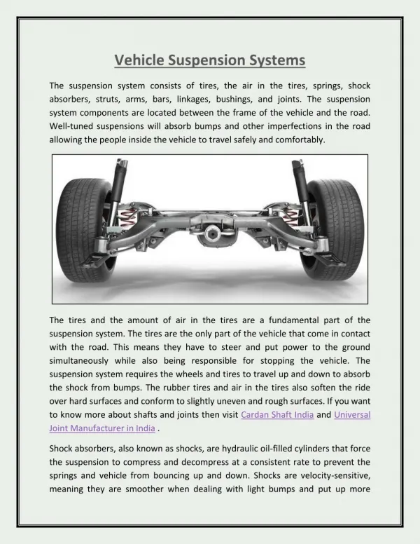
Download
1 / 48
640 likes | 1.23k Vues
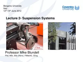
Bergamo University Italy 12 th -14 th June 2012. Lecture 2- Suspension Systems. Professor Mike Blundell Phd , MSc, BSc ( Hons ), FIMechE , CEng. Contents. Suspension Design Process Suspension Types Modelling Suspension Systems Measurements and Simulated Outputs.

E N D
Bergamo University Italy 12th-14th June 2012 Lecture 2- Suspension Systems Professor Mike Blundell Phd, MSc, BSc (Hons), FIMechE, CEng
Contents • Suspension Design Process • Suspension Types • Modelling Suspension Systems • Measurements and Simulated Outputs
Suspension Design Process Activities Wheel load variation - A classic case of static indeterminacy Front wheel drive hatchback cornering pose
Body Isolation –Ride Model • Proving Ground or Shaker Rig • Isolation and Comfort • Loss of Tyre/Ground Contact
Body Isolation – A Classical Quarter Vehicle Ride Model Vehicle Body or Sprung Mass • Predict Sprung Mass (Body) and Unsprung Mass (Wheel) Natural Frequencies • Transmissibility z m Body Response Suspension Spring and Damper c k Z zg Ground Input X Time (s)
Handling Load Control O1 Vy2 X1 • The simplest possible representation of a vehicle manoeuvring in the ground plane (bicycle model) • Weight transfer • Tyre lateral force characteristics as a function of tyre load GRF Vx2 Y1 Y2 X2 O2 G2 Fy wz2 Fy
Handling Load Control (Continued) • Side forces calculated for a 0.1 rads/s ramped input to 0.01 rads beginning at 0.3s Front axle side force Rear axle side force
Graphical Representation of Front Suspension Configurations in ADAMS/Chassis SLA (Coil) Hotchkiss McPherson Strut SLA (Torsion Bar) Twin I-Beam SLA (Perch) Provided courtesy of MSC.Software
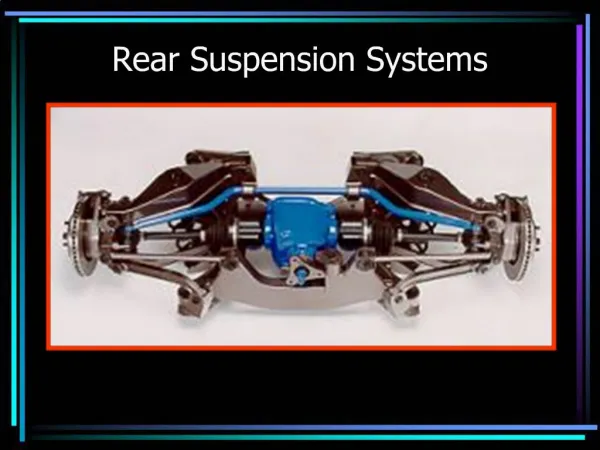
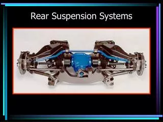
Graphical Representation of Rear Suspension Configurations in ADAMS/Chassis Central Link 4 Link Panhard 4 Link Watts Quardalink (Strut) Twist Beam Semi Trailing Arm Provided courtesy of MSC.Software
Double Wishbone Suspension System Upper Wishbone (Control Arm) Upper Bushes (Mounts) Upper Ball Joint (Bushes on Rear) Damper Wheel Knuckle (Stub Axle) (Kingpin) Spring Road Wheel Lower Bushes (Mounts) Lower Wishbone (Control Arm) Lower Ball Joint (Bushes on Rear) Connection to Rack (Body on Rear) Track Rod (Tie Rod on Rear) Track Rod End
McPherson Strut Suspension System Upper Mount Spring Damper Wheel Knuckle (Stub Axle) (Kingpin) Lower Bushes (Mounts) Road Wheel Lower Wishbone (Control Arm) Lower Ball Joint Connection to Rack Track Rod Track Rod End
Double Wishbone Suspension Modelled with Bushes Modelled with Bushes Modelled with Joints Bushes Spherical Revolute Spherical Bushes Revolute Revolute Revolute Spherical Spherical Motion Universal Motion Universal Spherical Spherical In-Plane In-Plane Motion Motion Translational Translational
Coventry UniversityFormula Student Car Bell Crank Push Rod Universal Revolute Spring Damper Spherical Body Mount Modelling of push rod and bell crank mechanism in student race car
Suspension AnalysisData Requirements Kinematic or Quasi-static vertical rebound to bump analysis Co-ordinates of suspension linkage connections Bush stiffnesses (If this effects the movement) Spring stiffness ( If suspension wheel rate is to be calculated) Static or Quasi-static durability analysis Co-ordinates of suspension linkage connections Bush stiffnesses Spring stiffness Bump and rebound stops Component flexibility (some suspensions) Dynamic durability or vibration analysis Co-ordinates of suspension linkage connections Mass and inertial properties Bush stiffnesses Bush damping coefficients Spring stiffness Damper properties Bump and rebound stops Component flexibility (some suspensions)
Use of Virtual Test Rig to Analyse a Half Vehicle Suspension Model Provided courtesy of MSC.Software Superimposed animation frames giving visual indication of wheel envelope
J Input of Vertical Motionat the Wheel Centre I Bump 100 Bump Movement (mm) In-Plane Motion 1.0 0.25 0.5 0.75 -100 Time (s) Rebound
Geometric and Instant Steer Axes of a Suspension System Geometric Steer Axis Instant Steer Axis
Bump Movement, Wheel Recession and Half Track Change Wheel Change Marker (WC) BM Fixed Ground Marker (FG) z y HTC BM = DZ(WC,FG) WC FG HTC = DY(WC,FG) z WR = DX(WC,FG) x WR
Half Track Change (HTC) • Influence in Vehicle Dynamics • Full Track Change effect • Beneficial on the outside wheel • Limits of bodywork A measure of how much the contact patch moves in and out relative to the vehicle body at bump movement Double Wishbone Mc Pherson BM = DZ(WC,FG) HTC = DY(WC,FG)
Influence in Vehicle Dynamics • Ride Comfort • Increased component durability A measure of fore-aft movement as the wheel moves between Bump and Rebound Wheel Recession (WR) Double Wishbone Mc Pherson WR= DX (WC, FG)
d d Calculation of Camber Angle and Steer Angle g g SA z g = (180/p) ATAN (DZ(WC,SA)/DY(SA,WC)) x WC y d =(180/p) ATAN (DX(WC,SA)/DY(SA,WC)) SA
As the vehicle rolls it’s needed to attempt and keep the tyre flat on the road and avoid opposite camber thrust the tyres running on their edges Camber angle (g) 0% Camber Rollover compensation 100% Camber Rollover compensation γ = (180/π) ATAN (DY(WC,SA)/DZ(SA,WC)) Double Wishbone Mc Pherson
As the suspension moves between bump and rebound small amounts of steer (toe) change may be introduced due to suspension geometry. It can be desirable to add to an understeer characteristic Bump (Roll) Steer (δ) δ = (180/π) ATAN (DY(WC,WB)/DX(WC,WB)) Double Wishbone Mc Pherson Gradient Shopping cars 4-5o/m Sport cars >10o/m
Calculation of Castor Angle and Suspension Trail f = (180/p) ATAN (DX(UB,LB)/DZ(UB,LB)) TR = DX(WB,LB) + DZ(LB,WB) * DX(UB,LB) / DZ(UB,LB) f Upper Ball Joint Marker (UB) Lower Ball Joint Marker (LB) z x Intersection of Steering Axis with Ground Wheel Base Marker (WB) TR
Castor Angle (φ) and Suspension Trail (TR) Castor angle adds to the self-centering with the Pneumatic Trail Suspension (Mechanical) Trail Typical Value 35-50mm Castor Angle change Double Wishbone Mc Pherson φ = (180/π) ATAN(DX(UB,LB)/DZ(UB,LB)) TR = DX (WB, LB) +DZ (LB, WB)*DX (UB, LB)/DZ (UB, LB)
Calculation of Steering Axis Inclination and Ground Level Offset q = (180/p) ATAN (DY(LB,UB)/DZ(UB,LB)) GO = DY(WB,LB) - DZ(LB,WB) * (DY(LB,UB) / DZ(UB,LB)) q UB z y GO Wheel Base Marker (WB) Intersection of Steering Axis with Ground
Steering Axis Inclination (θ) and Ground level Offset (GO) GO offset minimises scrubbing of the tyre during steering when stationary. Alternative method of tweaking GO is by using rims with offset.
When braking on split mu surface vehicle tends to yaw due to higher braking forces on the high mu side. Using negative ground level offset can compensate the effect. Steering Axis Inclination (θ) and Ground level Offset (GO) (continued) θ = (180/π) ATAN(DY(LB,UB)/DZ(UB,LB)) GO =DY (WB, LB)-DZ (LB, WB)*(DY (LB, UB)/DZ (UB, LB)) GO typical Value 10mm Double Wishbone Mc Pherson Front right wheel
Centre Line Centre Line z A A y B Instant Centre Roll Centre Height Instant Centre D C Roll Centre D C Roll Centre z y Roll Centre Height B Wheel Base (WB) Wheel Base (WB) Instant Centre and Roll Centre Positions Double Wishbone Suspension Double Wishbone Suspension McPherson Strut Suspension
B A Z WC X D C Y Position of Instant Centre Construction Points on Wheel Centre YZ Plane
RC is the corresponding point of lateral force application on the vehicle sprung mass and relative to its distance from the Vehicle’s CM is the applied roll torque. Height of Roll Centre (RC) Double Wishbone Mc Pherson
Fw VEHICLE BODY kw Fs kw dw ks Equivalent spring acting at the wheel centre A ds dw Fw ls lw Calculation of Wheel Rate (Equivalent Spring Acting at the Wheel Centre)
Wheel Rate The “equivalent” spring acting between wheel centre and the vehicle body Wheel rate can be set so as to be softer during initial bump and stiffer during increased bump travel for better ride comfort and roll control Double Wishbone Mc Pherson
Suspension Durability • Static Analysis Single Suspension System Model, Range of Load Cases (3G Bump, 2G Rebound, 1G Braking, ….) • Dynamic Analysis using Road Load Data Single Suspension System Model, Quarter or Full Vehicle Model • Full Virtual Modelling and Analysis for Durability Full Vehicle Model with Transient Dynamics Physical Tyre Model Required Road/ Terrain model (Laser scanned)
Fy Lateral loads Fx Longitudinal loads Fz Vertical loads Suspension Durability Analysis LOADCASE Fx (N) Fy (N) Fz (N) 3G Bump 11180 2G Rebound -7460 0.75G Cornering 4290 5880 (Outer Wheel) 0.75G Cornering -1180 1620 (Inner Wheel) 1G Braking 5530 5530 0.35G Reverse -2150 3330 Braking Kerb Impact 9270 4120 Pothole Braking 15900 12360 Garrett, T. K., (1953) Automobile dynamic loads some factors applicable to design, Automobile Engineer, February.
cm mAx Z h mg FRx FFx X FRz = FSRz – FB FFz = FSFz + FB a b L Weight Transfer-Braking Hand calculations can be performed To establish loads for braking or cornering FFz= FSFz + FB = + FRz = FRFz – FB = - FFx = m FFz FFx = m FFz
UNI REV SPH BUSH SPH CYL BUSH BUSH REV FIX BUSH MOTION SPH I marker at wheelbase 15900 N ZP for marker 3 12360 N Z ZP for marker 1 GRF X Y ZP for marker 2 Case Study - Pothole Braking Case • Ramping loads on over 1 second (Quasi-static) • Allows animation (visual check) • Load path through damper not modelled • Unless static equivalent force included
Quarter Vehicle Body Part Body connects to Ground by Translational Joint Jack Part Quarter Vehicle Model Simple starting pointDynamic AnalysisRoad Bump StrikeTyre stiffness and dampingTyre can lift off
10 m/s GRF Z X 1000 200 200 200 200 10000 200 200 y . . . . . . . . . 8 7 1 2 5 4 3 6 9 150 x Point123456789 Distance x (mm)0 1000 1200 1400 1600 1800 2000 2200 12200 Time x (s) 0 0.10 0.12 0.14 0.16 0.18 0.20 0.22 1.22 Height y (mm)0075 150 150 150 75 0 0 Road Profile
Time = 0.14 sec Time = 0 sec Time = 0.18 sec Quarter Model Results