Download

1 / 48
831 likes | 2.03k Vues
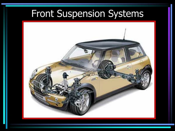
115. ELECTRONIC SUSPENSION SYSTEMS. Figure 115-1 An electronically controlled suspension system can help reduce body roll and other reactions better than most conventional suspension systems.

E N D
115 ELECTRONIC SUSPENSION SYSTEMS
Figure 115-1 An electronically controlled suspension system can help reduce body roll and other reactions better than most conventional suspension systems.
Figure 115-2 Input devices monitor conditions and provide information to the electronic control module, which processes the information and operates the actuators to control the movement of the suspension.
Figure 115-3 A typical electronic suspension height sensor, which bolts to the body and connects to the lower control arm through a control link and lever.
Figure 115-4 When suspension action moves the lever, it rotates the slotted disc and varies how much of the photo transistor is exposed to the LEDs, which vary the input signal.
Figure 115-6 A three-wire suspension position sensor schematic.
Figure 115-8 The steering wheel position (handwheel position) sensor wiring schematic and how the signal varies with the direction that the steering wheel is turned.
Figure 115-9 The handwheel position sensor is located at the base of the steering column.
Figure 115-10 Steering wheel (handwheel) position sensor schematic.
Figure 115-11 The VS sensor information is transmitted to the EBCM by Class 2 serial data.
Figure 115-13 A schematic showing the lateral acceleration sensor and the EBCM.
Figure 115-14 A visual inspection showed a liquid had spilled. This lead to finding the lateral acceleration sensor connector terminals were corrorded.
TECH TIP: A Visual Inspection Is Often the Key to Success. An ABS amber warning light and a stored U0124 code (lost communications with lateral acceleration sensor) lead to looking at service information for the location of the sensor. It was found to be located under the center console. A visual check of the area showed that a sticky soft drink had likely spilled from the cup holder. - SEE FIGURE 115–14 . The liquid had gotten into the electrical connector and caused the fault.
Figure 115-15 Yaw rate sensor showing the typical location and schematic.
Figure 115-16 A magnetic field is created whenever an electrical current flows through a coil of wire wrapped around an iron core.
Figure 115-17 When magnets are near each other, like poles repel and opposite poles attract.
Figure 115-18 When electrical current magnetizes the plunger in a solenoid, the magnetic field moves the plunger against spring force. With no current, the spring pushes the plunger back to its original position.
Figure 115-19 This air supply solenoid blocks pressurized air from the air spring valves when off. The plunger pulls upward to allow airflow to the air spring valves when the solenoid is energized.
Figure 115-20 An actuator motor uses a permanent magnet and four stator coils to drive the air spring control rod.
Figure 115-21 The stator coils of the actuator are energized in three ways to provide soft, medium, or firm ride from the air springs and shock absorbers.
Figure 115-22 Selectable Ride as used on Chevrolet and GMC pickup trucks.
Figure 115-23 ALC maintains the same ride height either loaded or unloaded by increasing or decreasing the air pressure in the rear air shocks.
Figure 115-24 A typical schematic showing the air suspension compressor assembly and sensor.
Figure 115-25 The typical variable-rate air spring system uses three height sensors, two in the front and one in the rear, to monitor trim height and to provide input signals to the ECM.
Figure 115-26 The air spring compressor assembly is usually mounted on rubber cushions to help isolate it from the body of the vehicle. All of the air entering or leaving the air springs flows through the regenerative air dryer.
Figure 115-27 A solenoid valve at the top of each spring regulates airflow into and out of the air spring.
Figure 115-28 Schematic showing Computer Command Ride (CCR) system.
Figure 115-29 Schematic showing the shock control used in the RSS system.
TECH TIP: Check the RPO Code Whenever working on the suspension system check the RPO (regular production option) code for the type of suspension used. For example, the F55 RPO may be called by a different name depending on the make and model of vehicle. Also, service procedures will be different on the same vehicle depending on whether it is equipped with an F45 or an F55 system. The General Motors vehicle RPO codes are on a sticker on the spare tire cover in the trunk or in the glove compartment.
Figure 115-30 Bi-state dampers (shocks) use a solenoid to control fluid flow in the unit to control compression and rebound actions.
Figure 115-31 Solenoid valve controlled shock absorber circuit showing the left front (LF) shock as an example.
Figure 115-33 The three dampening modes of a CCR shock absorber.
FREQUENTLY ASKED QUESTION: What Are Self-Leveling Shocks? A German company, ZF Sachs, supplies a self-leveling shock absorber to several vehicle manufacturers, such as Chrysler for use on the rear of minivans, plus BMW, Saab, and Volvo. The self-leveling shocks are entirely selfcontained and do not require the use of height sensors or an external air pump. - SEE FIGURE 115–35 . The shock looks like a conventional shock absorber but contains the following components: • Two reservoirs in the outer tube • An oil reservoir (low-pressure reservoir) • A high-pressure chamberInside the piston rod is the pump chamber containing an inlet and an outlet valve. When a load is placed in the rear of the vehicle, it compresses the suspension and the shock absorber. When the vehicle starts to move, the internal pump is activated by the movement of the body. Extension of the piston rod causes oil to be drawn through the inlet valve into the pump. When the shock compresses, the oil is forced through the outlet valve into the high-pressure chamber. The pressure in the oil reserve decreases as the pressure in the high-pressure chamber increases. The increasing pressure is applied to the piston rod, which raises the height of the vehicle. When the vehicle’s normal height is reached, no oil is drawn into the chamber. Because the shock is mechanical, the vehicle needs to be moving before the pump starts to work. It requires about 2 miles of driving for the shock to reach the normal ride height. The vehicle also needs to be driven about 2 miles after a load has been removed from the vehicle for it to return to normal ride height.
Figure 115-35 A typical ZF Sachs self-leveling shock, as used on the rear of a Chrysler minivan.
Figure 115-37 Air compressor assembly can be located at various locations depending on the vehicle.
Figure 115-38 The exhaust solenoid is controlled by the rear integration module (RIM).
Figure 115-39 Schematic showing the rear integration module (RIM) and how it controls the ALC compressor.
Figure 115-40 Vehicles that use magneto-rheological shock absorbers have a sensor located near each wheel, as shown on this C6 Corvette.
Figure 115-41 The controller for the magneto-rheological suspension system on a C6 Corvette is located behind the right front wheel.
FREQUENTLY ASKED QUESTION: Can Computer-Controlled Shock Absorbers and Struts Be Replaced with Conventional Units? Maybe. If the vehicle was manufactured with or without electronic or variable shock absorbers, it may be possible to replace the originals with the standard replacement units. The electrical connector must be disconnected, and this may cause the control system to store a diagnostic trouble code (DTC) and/or turn on a suspension fault warning light on the dash. Some service technicians have used a resistor equal in resistance value of the solenoid or motor across the terminals of the wiring connector to keep the controller from setting a DTC. All repairs to a suspension system should be done to restore the vehicle to like-new condition, so care should be exercised if replacing electronic shocks with nonelectronic versions.
Figure 115-42 A cutaway of a magneto-rheological shock absorber as displayed at the Corvette Museum in Bowling Green, Kentucky.
Figure 115-43 Most electronic level-control sensors can be adjusted, such as this General Motors unit.