Electronic systems
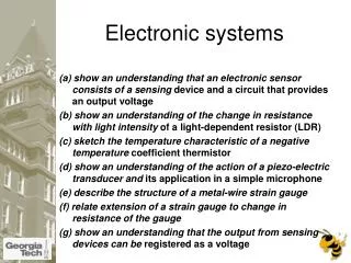
Electronic systems. (a) show an understanding that an electronic sensor consists of a sensing device and a circuit that provides an output voltage (b) show an understanding of the change in resistance with light intensity of a light-dependent resistor (LDR)

Electronic systems
E N D
Presentation Transcript
Electronic systems (a) show an understanding that an electronic sensor consists of a sensing device and a circuit that provides an output voltage (b) show an understanding of the change in resistance with light intensity of a light-dependent resistor (LDR) (c) sketch the temperature characteristic of a negative temperature coefficient thermistor (d) show an understanding of the action of a piezo-electric transducer and its application in a simple microphone (e) describe the structure of a metal-wire strain gauge (f) relate extension of a strain gauge to change in resistance of the gauge (g) show an understanding that the output from sensing devices can be registered as a voltage
Sensors • LDR (203) • Thermistor (199) • Strain gauge (203) • Potential divider (p210)
Operational Amplifiers (h) recall the main properties of the ideal operational amplifier (op-amp) (i) deduce, from the properties of an ideal operational amplifier, the use of an operational amplifier as a comparator (j) show an understanding of the effects of negative feedback on the gain of an operational amplifier (k) recall the circuit diagrams for both the inverting and the non-inverting amplifier for single signal input (l) show an understanding of the virtual earth approximation and derive an expression for the gain of inverting amplifiers. (m) recall and use expressions for the voltage gain of inverting and of non-inverting amplifiers.
What is an Op-Amp? – The Surface • An Operational Amplifier (Op-Amp) is an integrated circuit that uses external voltage to amplify the input through a very high gain. • We recognize an Op-Amp as a mass-produced component found in countless electronics. What an Op-Amp looks like to a lay-person What an Op-Amp looks like to an engineer
What is an Op-Amp? – The Layout • There are 8 pins in a common Op-Amp, like the 741 which is used in many instructional courses.
What is an Op-Amp? – The Inside • The actual count varies, but an Op-Amp contains several Transistors, Resistors, and a few Capacitors and Diodes. • For simplicity, an Op-Amp is often depicted as this: Positive Power Supply Inverting Input - Output + Non-Inverting Input Negative Power Supply
History of the Op-Amp – The Dawn • Before the Op-Amp: Harold S. Black develops the feedback amplifier for the Western Electric Company (1920-1930) Forward Gain A Input Output β Feedback
History of the Op-Amp – The Dawn • The Vacuum Tube Age • The First Op-Amp: (1930 – 1940) Designed by Karl Swartzel for the Bell Labs M9 gun director • Uses 3 vacuum tubes, only one input, and ± 350 V to attain a gain of 90 dB • Loebe Julie then develops an Op-Amp with two inputs: Inverting and Non-inverting
History of the Op-Amp – The Shift • The end of Vacuum Tubes was built up during the 1950’s-1960’s to the advent of solid-state electronics • The Transistor • The Integrated Circuit • The Planar Process
History of the Op-Amp – The Shift • 1960s: beginning of the Solid State Op-Amp • Example: GAP/R P45 (1961 – 1971) • Runs on ± 15 V, but costs $118 for 1 – 4 • The GAP/R PP65 (1962) makes the Op-Amp into a circuit component as a potted module
History of the Op-Amp – The Evolution • The solid-state decade saw a proliferation of Op-Amps • Model 121, High Speed FET family, etc. • Robert J. Widlar develops the μA702 Monolithic IC Op-Amp (1963) and shortly after the μA709 • Fairchild Semiconductor vs. National Semiconductor • National: The LM101 (1967) and then the LM101A (1968) (both by Widlar) • Fairchild: The “famous” μA741 (by Dave Fullager 1968) and then the μA748 (1969)
(h) recall the main properties of the ideal operational amplifier (op-amp)
Mathematics of the Op-Amp • The gain of the Op-Amp itself is calculated as: G = Vout/(V+ – V-) • The maximum output is the power supply voltage • When used in a circuit, the gain of the circuit (as opposed to the op-amp component) is: Av = Vout/Vin
741 Op-Amp Schematic current mirror current mirror voltage level shifter output stage current mirror high-gain amplifier differential amplifier
Ideal Op-Amp Characteristics • Open-loop gain G is infinite • Rinis infinite • Zero input current • Rout is zero • Infinite bandwidth (same amplification for all frequencies) • Infinite slew rate (How fast the op amp reacts)
Op-Amp Characteristics • Open-loop gain G is typically over 9000 • But closed-loop gain is much smaller • Rin is very large (MΩ or larger) • Rout is small (75Ω or smaller) • Effective output impedance in closed loop is very small
Ideal Op-Amp Analysis • To analyze an op-amp feedback circuit: • Assume no current flows into either input terminal • Assume no current flows out of the output terminal • Constrain: V+ = V-
(i) deduce, from the properties of an ideal operational amplifier, the use of an operational amplifier as a comparator
Basic comparator • Vo=Ao(V+-V-) • Ao is very large • So output is usually saturated • Polarity depends on which input has biggest magnitude
Op-Amp Saturation Vout • As mentioned earlier, the maximum output value is the supply voltage, positive and negative. • The gain (G) is the slope between saturation points. Vs+ Vin Vs-
Basic comparator • The potential divider provides a fixed input to V+ • The V- input will “be compared” • If V in is larger than V+ output is negative • Try some values with the equation eg V+= 5V Vin= 5.5V (assume an open loop gain of 105) • What happens when Vin is less than V+?
Using a potential divider to provide Vin • By using a potential divider circuit connected to the same power supply as the reference input.
To do • Draw a circuit using an operational amplifier to provide a positive output when it is hot and a negative output when it is cold. • Try the past paper question (Nov 2007 p4q9)
(j) show an understanding of the effects of negative feedback on the gain of an operational amplifier (k) recall the circuit diagrams for both the inverting and the non-inverting amplifier for single signal input
Inverting Amplifier Analysis virtualearth To avoid saturation Vin must be very nearly equal to V+ (i.e. V) Hence virtual earth
Inverting Amplifier Analysis virtualground • Since impedence of the op amp is very high no current flows through the device. • Current through Rin=Current through Rf • Positive values of Vin give –ve output values and vice-versa. (Can you use the equation to show why?)
Inverting Amplifier Analysis • Iin+If • V(Rin)/Rin=V(Rf)/Rf • Since P=OV • V(Rin)= Vin-0 • V(Rf)= 0-Vout • So Vout/Vin=-Rf/Rin P (virtualground)
To do • Look cover check the derivation. • Explain in a simple paragraph what is meant by “virtual earth” (hint use bullet points) • Try questions from Understanding Physics (p529 25.5 +25.6, p547 EM19 +20)
Op-Amp Differential Amplifier If R1 = R2 and Rf = Rg:
Applications of Op-Amps • Electrocardiogram (EKG) Amplification • Need to measure difference in voltage from lead 1 and lead 2 • 60 Hz interference from electrical equipment
Applications of Op-Amps • Simple EKG circuit • Uses differential amplifier to cancel common mode signal and amplify differential mode signal • Realistic EKG circuit • Uses two non-inverting amplifiers to first amplify voltage from each lead, followed by differential amplifier • Forms an “instrumentation amplifier”
Strain Gauge Use a Wheatstone bridge to determine the strain of an element by measuring the change in resistance of a strain gauge (No strain) Balanced Bridge R #1 = R #2 (Strain) Unbalanced Bridge R #1 ≠ R #2
Strain Gauge Half-Bridge Arrangement Op amp used to amplify output from strain gauge R + ΔR Rf R Vref + Vcc + - + V0 __ + - - Vcc R R - ΔR Rf Using KCL at the inverting and non-inverting terminals of the op amp we find that ε ~ Vo = 2ΔR(Rf /R2)
References • Cetinkunt, Sabri. Mechatronics. Hoboken, NJ: John Wiley & Sons Inc., 2007. • Jung, Walter G. Op Amp Applications Handbook. Analog Devices, Inc., 2005. • “Operational Amplifier.” http://en.wikipedia.org/wiki/Operational_amplifier. • “Operational Amplifier Applications.” http://en.wikipedia.org/wiki/Operational_amplifier_applications.
References • Rizzoni, G. Principles and Applications of Electrical Engineering, McGraw Hill, 2007. • http://web.njit.edu/~joelsd/electronics/Labs/ecglab.pdf
Output (n) show an understanding of the use of relays in electronic circuits (o) show an understanding of the use of light-emitting diodes (LEDs) as devices to indicate the state of the output of electronic circuits (p) show an understanding of the need for calibration where digital or analogue meters are used as output devices.
Objectives • Know the definition of a relay • Understand relay operating principles • Properly test relay operation
Relay Principles • A relay may also be called an “electromagnetic switch” • Relays use a “low current circuit” to control a “high current circuit” • The low current circuit controls an electromagnetic device • The electromagnetic device “closes/opens” the high current circuit
REVIEW... • WHY ARE RELAYS CALLED MAGNETIC SWITCHES? • HOW MUCH CURRENT DOES THE CONTROL CIRCUIT USE? • HOW MUCH CURRENT DOES THE LOAD CIRCUIT USE? • NAME SOME ADVANTAGES OF USING RELAYS?