Software-Defined GPS Receiver: Implementation and Results
470 likes | 565 Vues
Explore the implementation of a software-defined GPS receiver, advantages of cost reduction and upgradeability, system components, position calculation progress, and results. The focus is on signal acquisition, tracking, and positioning.

Software-Defined GPS Receiver: Implementation and Results
E N D
Presentation Transcript
Implementation of a Software-defined GPS Receiver Anthony J. Corbin Dr. In Soo Ahn Friday, October 31, 2014
Overview • Rationale • System Description • Software Architecture • Coarse Acquisition • Fine Acquisition • Tracking • Positioning • Progress/Results • Conclusion/Achievements
Rationale • Reduce Cost • Eliminates ASICs or other custom ICs • More Upgradeable • GPS Block III • Galileo
Cost • Cost is driving the mass-adoption of GPS devices • Currently, a GPS chipset in volume costs around $5 8 • The software GPS chipset, which is currently being produced in low volume, costs around $4 2 • In high-volume, the cost of a software GPS chipset would likely become negligible
Upgradeable • China and the European Union are developing their own systems7 • Russia already has its own system, but is working on making it more compatible with other systems6 • The U.S. is beginning work on Block III GPS satellites • For a software-defined receiver, a simple software patch would be, in many cases, sufficient to use these systems
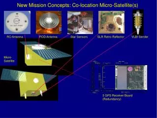
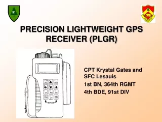
USB GPS Dongle • USB 2.0 Interface • Simple software interface
Position Error • Estimated position is based on the sampling rate being 4 times the chipping rate. • ¼ of the distance represented by a chip is therefore the approximate error.
Time to First Fix [1] • A position fix requires that the ephemeris data is completely received. • This requires a complete frame of data, which takes 30 s to transmit. • However, it is unlikely that the receiver shall begin collecting data at the beginning of a subframe indicating that an extra subframe lasting 6 s must be received. • If the ephemeris data has already been received, the fix time is minimal.
Coarse/Acquisition Code Generation • A generated C/A code sample is shown to the right. • The signal generated is based on the pseudorandom sequence generation shown on the next slide.
Coarse Acquisition • Coarse acquisition searches around the intermediate frequency in the range +/- 10 KHz with a step of 500 Hz • Frequency Domain Correlation
Frequency Domain Correlation • The correlation value must be checked at every code alignment. • To perform this quickly, the operation is performed in the frequency domain. • As shown in the right, cross-correlation is equivalent to the product of X*(w) and Y(w) in the frequency domain.
C/A Code Characteristics • Repeats every 1023 chips • Cross-correlation between two satellites’ C/A codes is minimal • Correlation value is only large when the code is perfectly aligned with itself.
Cross-Correlation • The first 3D graph shows the cross-correlation between C/A codes for different satellites for the perfectly aligned case, while the second shows a misaligned case. • The crest in the first graph shows correlation values for the same satellite in the perfectly aligned case.
Correlation Result • The graph to the right shows the results of a correlation between sample data and a known C/A code • The large peak indicates the proper code alignment
Fine Acquisition • Uses the frequency estimate from Coarse Acquisition to obtain a more accurate estimate
Tracking • Tracking occurs in the time domain • A Delay-Locked Loop tracks the Code Frequency • A Phase-Locked Loop tracks the Carrier Frequency
Delay-Locked Loop [1] • The DLL tracks the Code Frequency by generating two extra C/A code sequences • The extra sequences are shifted slightly early and slightly late with respect to the prompt sequence • The differences in the correlation values, as shown below, indicates the direction in which the prompt sequence must be shifted
C/A Code Tracking • The graphs to the right show the code error output from the delay-locked loop. • The loop parameters have been refined through testing to allow for fast convergence.
Carrier Tracking • A carrier error signal is shown on the right. • In this example, the frequency of the carrier appears to be drifting further below the intermediate frequency. • This is due to the Doppler Effect.
Navigation Data • The figures to the right show resolved 50 Hz navigation data after coarse acquisition, fine acquisition, tracking, and post-processing has occurred. • The top graph shows 32s of data, while the bottom graph shows 3s.
Progress • MATLAB GPS software [1] has been ported to C++ • This includes: • Coordinate conversion • Tracking loop • Acquisition algorithms • DSP design approach was abandoned due to technical issues at a very early stage of the project. • C++ code can accurately find a position from stored sample data. • Developed code has been restructured to run in parallel.
Position Results 51.81 m
Position Results 104.4 m
Speed • Currently the C++ code requires under a minute (per satellite) to read a full 36 s of satellite data. • Compare this with the Matlab code which takes 6 minutes per satellite.
Intel Threading Building Blocks • Intel’s TBB is a library for creating threaded programs • Platform independent • Relatively easy to use
Changes to Project Objectives • Finding the satellite positions requires an accurate time…requiring collection of at least subframes 1-3 of the ephemeris data • The equation below shows the number of multiplications per second required to track one satellite. This does not include C/A code generation, carrier demodulation, or the overhead involved with sampling. • The DSP considered is clocked at 225 MHz which is simply not fast enough.
Scheduling • Telemetry and Handover words contain a Time-of-Week value that can be used to update the position of the satellites • The TLM/HOW words are sent at the beginning of each subframe which occurs every 6 seconds
Scheduling • Scheduling allows a minimal set of data to be used for position computation • Orbital data is typically valid for several hours
Conclusions • Results show that implementation is practical on modern PCs • However, application in low cost embedded systems is several years out
Achievements • Successful determination of position • Real-time satellite availability determination • Working C++ based receiver code • Stored data • Received data using USB sampler • Wrapped the driver code for the USB device in C++ • Multi-threaded object-oriented design • Google Earth C++ class wrapper
Recommendations for Future Work • Continue enhancing code for further improvements. • Research neural network approaches.
References • [1] Kai Borre, Dennis M. Akos, Nicolaj Bertelsen, Peter Rinder, and Soren Holdt Jensent, Software-Defined GPS and Galileo Receiver : A Single-Frequency Approach. Birkhauser: Boston, 2007, pp. 29, 83, 105. • [2] SiGe, SE4110L-EK1 Evaluation Board User Guide. • [3] SiGe, SE4110L Datasheet. • [4] U.S. DoD, Navstar GPS Space Segment/Navigation User Interfaces. IS-GPS-200 Rev. D. • [5] U.S. DoD, World Geodetic System 1984 : Its Definition and Relationships with Local Geodetic Systems • [6] Wikipedia, GLONASS. <http://en.wikipedia.org/wiki/GLONASS> • [7] Wikipedia, GALILEO. <http://en.wikipedia.org/wiki/Galileo_gps> • [8] EDACafe.com. Atmel Introduces $5 GPS Baseband IC With 3 Meter Accuracy. <http://www10.edacafe.com/nbc/articles/view_article.php?articleid=177910&page_no=2>