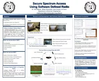
Implementing Software Defined Radio for Enhanced Wireless Communication Calibration
This project explores the implementation of Software Defined Radio (SDR) modules for enhanced wireless communication capabilities. We focus on calibrating power, frequency, and phase using M-sequences and rigorous signal processing techniques. The system design integrates hardware components like the TMS320F28335 Digital Signal Controller for processing I and Q values, ensuring reliable data packet transmission. Through advanced modulation techniques, including BPSK and I/Q modulation, we achieve optimal signal performance, adjusting in real-time to varying conditions in the communication channel.

Implementing Software Defined Radio for Enhanced Wireless Communication Calibration
E N D
Presentation Transcript
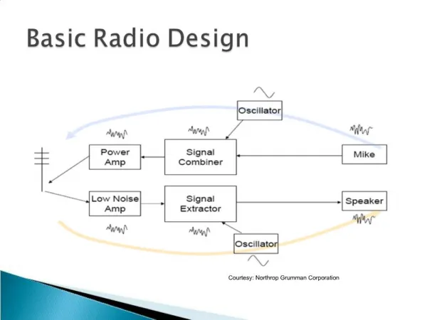
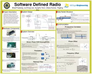
Used for power calibration Stuck in this mode until Tx sends Software Defined Radio Turn On Rx found m-seq Phase correction Frequency correction Look for M-seq Initial start up 12500 samples Brad Freyberg, JunYong Lee, SungHo Yoon, Uttara Kumar, TingtingZou After GFX routine is finished, set mseq_found = 0 Receiving & decoding data ● Fill up character array(data) (fixed length) ● Save I, Q decision samples User triggers 1st m-seq Filter g(t) I Print GFX ● Print character array ● Print full I, Q ●“animate” the drawing Data Packet Structure System Design Time varying IQ values Project Description ΔƟ_total Modulated Carrier Detected I,Q values packet countdown >0 Ɵ Filter g(t) M-sequence This field specifies the 15 bit correlation sequence which detects the start of the data packet . Used for frequency, phase and timing calibration Packet no. : This field helps the receiver to keep track of the number of packets that are yet to arrive. For eg. a 2 in this field would inform that receiver that 2 data packets are to follow the current one and a value 0 indicates end of transmission. Data: This field contains the actual data being sent from the transmitter. The goal of our project is to implement the communication modules, that constitute a traditional radio, in software and to successfully demonstrate wireless communication using our system. Software Defined Radio attempts to place much or most of the complex signal handling involved in communications receivers and transmitters into software. Doing this allows these radios to be configured ‘on-the-fly’ providing the much needed flexibility which is the growing demand of any modern communication system today. Fixed IQ values Q Correct I,Q values Turn On Tx 128 bits First byte after m-seq (packet countdown)is # of packets to expect Data ( 15 bytes ) M-sequence Packet no. packet countdown =0 Data array is filled 15 bits 8 bits Synchronization M-sequence Correlator Hardware Components Peaks representing sample boundaries are matched up. Compare the slope with a threshold slope. The slope threshold: In the first 12500 samples (=2500 samples * 5 sec),the maximum value(power) is detected. Based on this, we calculate attenuation factor by comparing with the maximum power of wired communications. Slope threshold = Attenuation factor * MSEQ_SLOPE_THRESHOLD If (current slope > predefined slope threshold), m-sequence is detected. System Overview TMS320F28335DSC All of our software modules are implemented on this 150 MHz floating point TI Digital Signal Controller It has 2 on-chip 12 bit, 16 channel ADCs with 2 parallel sample and hold circuits ideal for IQ modulation 6 high resolution PWM pins combined with a low pass filter are configured as the DACs in our system Phase Offset Binary Phase Shift Keying(BPSK) Modulation Phase-shift keying has information in the phase of sinusoidal waveform. In BPSK , the phase of the RF carrier is shifted 180 degrees in accordance with a digital bit stream. Conveys information using two distinct phases (π and 0) Modulation is the process by which some characteristic (frequency, phase, amplitude, or combinations thereof) of a carrier frequency is varied in accordance with a digital signal. Inphase-Quadrature modulation: Transmit 2 carrier sinusoids phased shift by 90 degrees – Inphase component and Quadrature component. Carriers modulate the digital data to produce the I and Q waveforms. Reason : No information of the transmitted signal’s phase at the receiver side When the peak is found, we take the latest I,Q sample from the matched filter. I, Q samples represent the last bits of m-sequence, so we correct the I, Q samples by measuring degree difference on the IQ plot. • IQ modulator • This board essentially modulates the I and Q waveforms to carrier frequency of 500Mhz • Inputs : Clock, I and Q waveforms • Outputs: Modulated waveform to the antenna tuner board Frequency Offset Reason : The frequency of the oscillators at the transmitter and receiver is not exactly same When the peak is found, we take every alternate of the last samples of the m-sequence. M-sequence: [1, 0, 0, 0, 1, 0, 0, 1, 1, 0, 1, 0, 1, 1, 1] Used Linear Regression Equation to estimate frequency offset per a bit: • Spartan-3 FPGA • Connected directly to the DSC through SPI bus • Configured to graph the received data on the IQ constellation plot through a VGA display Matched Filter The signal at the receiver is affected by noise resulting in a low SNR. Sampling this received waveform may result in a ‘0’ being interpreted as a ‘1’ or vice versa causing errors. SOLUTION ? Matched filter is an optimal linear filter that maximizes the signal-to-noise ratio(SNR) in AWGN channel Concept behind it : Calculate the correlation between the signal and filter maximize the inner product minimize the effect of channel noise increase SNR • Antenna Tuner Board • The RF front end that tunes the antenna to the carrier frequency • It has OpAmps on it for magnifying received signal I and Q waveforms passed through the Matched filter in our system