Software Defined Radio
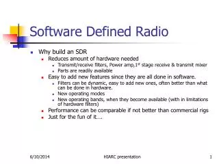
Software Defined Radio. Why build an SDR Reduces amount of hardware needed Transmit/receive filters, Power amp,1 st stage receive & transmit mixer Parts are readily available Easy to add new features since they are all done in software.

Software Defined Radio
E N D
Presentation Transcript
Software Defined Radio • Why build an SDR • Reduces amount of hardware needed • Transmit/receive filters, Power amp,1st stage receive & transmit mixer • Parts are readily available • Easy to add new features since they are all done in software. • Filters can be dynamic, easy to add new ones, often better than what can be done in hardware. • New operating modes • New operating bands, when they become available (with in limitations of hardware filters) • Performance can be comparable if not better than commercial rigs • Just for the fun of it…. HIARC presentation
Quantum Software Defined Radio • Hardware Architecture • Overview, Features & Flow • Board schematics & photos • Decoder SPICE Simulations • Encoder SPICE Simulations • Software Architecture • Overview, Features & Flow • Demodulation & Modulation Algorithms • SDR Operation • AM & SSB photos • To Do list • Demo HIARC presentation
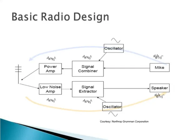
Hardware Overview Band Filter Selection 10/20db Amp & TX/RX USB based Controller VFO 0.5-54Mhz Filters Quadrature Encoder / Decoder Pre-Selector RX Preamp, 1st TX Amp Power Amp I/Q Audio to PC, I/Q From PC RF In/Out HIARC presentation
Hardware Features • USB interface • Controller acts as low speed HID device • Can be interfaced to Windows, LINUX and MAC without drivers • RX gain adjustable on decoder & will add preamp to pre-selector • Ham band filters to be used in the pre-selector • 500KHz to 54MHz continuous • < 1 Hz steps possible • Off the shelf parts • Most parts available from Digikey or Mouser • DDS available direct from Analog Devices, Transformer from MiniCircuits • PI5V331 from All American Direct (min $50 order) • Low phase noise, low noise DDS (AD9854) used (< -100 dbm,<25 pS rms jitter). • Low phase noise, low noise 72MHz oscillator used ,4x PLL used on DDS to raise internal clock to 284MHz @ the expense of an extra 350mA. • DDS (AD9854) simplifies hardware by providing I & Q clock signal for encoder & decoder clock • Designed to function as 2 Receiver, 1 Transmitter radio • Will add >40db gain exciter to drive PA • Receiver sensitivity measured @ ~ -115dBm (10db S/N) • VFO & image signals ≤ -50dB from signal during transmit HIARC presentation
Hardware flow RX • Incoming RF is filtered by pre-selector. • 1:4 transformer before decoder adds 12db gain • Decoder performs sample/hold, breaks signal in to 4 phases, mixing signal to audio range. • 0o & 180o phases differentially added to make I, 90o & 270o phases differentially added to make Q • ‘Mixer’ adds 1-2db gain • High Q • Bandwidth set by • Instrumentation amps add 10db/20db more gain • Overall RX gain measured to be about 23db (with 10db from Instrumentation amps) • PC performs A/D, filtering, demodulation, AGC, squelch & etc HIARC presentation
Hardware flow • TX • PC performs modulation, filtering, compression & leveling & etc, Creates I & Q, D/A • DRV135 driver buffers/adds 6db of gain to compensate for 4:1 transformer • Creates 0o, 90o, 180o & 270o phases from I/Q • Encoder mixes signal up to RF range set by VFO frequency. • Signal filtered & amplified to get enough drive for PA • Signal further amplifier & filtered before radiated into the ether HIARC presentation
Controller Schematic HIARC presentation
VFO Schematic HIARC presentation
Encoder/Decoder Schematic HIARC presentation
Spice RX Simulations 1.01MHz Carrier, 2.5 KHz Modulation, VFO @ 1.0 MHz ( I & Q output + 800uV rms AM incoming signal shown) HIARC presentation
Spice RX Simulations 1.01MHz Carrier, 2.5 KHz Modulation, VFO @ 1.0 MHz ( I & Q output + 800uV rms AM incoming signal shown) HIARC presentation
Measured SDR Decoder Response HIARC presentation
Measured Encoder Response HIARC presentation
Spice TX Simulations: 1.0MHz VFO, 0.3VRMS, 2.5 KHz Modulation ( 4 phase inputs to PI5V331 & RF signal shown) HIARC presentation
VFO Board HIARC presentation
VFO Board HIARC presentation
VFO Board HIARC presentation
Encoder/Decoder Board HIARC presentation
Encoder/Decoder Board HIARC presentation
Program Architecture Wave File (I & Q) data I &Q from decoder to Line In Sound Class Mono Audio Stereo Audio Speakers Signal Processing Class UI Class Wave Volume & Input Gain Settings stored by band & mode Filter Settings Class Mixer Class Filter Settings File HIARC presentation
Software flow (Receive) • IF signal is digitized by the Sound card, @ 44.1Khz, 16bit/sample stereo (for I & Q) • Data sampled in 2048 bytes, 10.7Hz resolution • Program converts data to ‘double’ for numerical processing • Previous data set spectrum data is plotted • FFT, converts to polar coordinates. • IF shifted by 11.025KHz, zero out unused side band • Band Pass & Notch filters applied • Data ‘thinned’ and saved for plotting • Translate back to Cartesian, Inverse FFT • Audio processing • Demodulation • Squelch, AGC & Noise filtering • Audio data is converted back to integer and sent to sound card for playback • Playback buffer buffered by 1 sample so total delay is 92 mS HIARC presentation
Software Features/Requirements • Uses Readily available (free) libraries & tools • DirectX 8 SDK, Windows Device Driver DDK (for USB HID library) • Digital Mars D Compiler (free www.digitalmars.com) • Intel NSP Library (free for non commercial use) • Requires ~ 800MHz P3 or better • Any mode that can fit in to 15KHz bandwidth can be RX’d / TX’d • Limitation of 1/f noise, depending on where IF is defined • Easy to add new bands & operating modes • Digital Filters offering, adjustable BW, sharp contours, user configurable • Capture & play back OTA signals in I & Q form. • Software could support 2 receivers boards • Real time color coded Spectrum analyzer • Control of sound card input gain and output volume • Adjustable AGC & Squelch • In band split operation • Memories • Saves filter & mode settings for each memory entry • Control over pre amplifier stages HIARC presentation
Features currently implemented • Hardware • USB controller, 1 VFO • 1 Receiver, 1 Transmitter • Decoder pre-Amp • Software • AM, FM , LSB, USB, CW receive • AGC • Adjustable band pass, 2 notch filters (in the frequency domain), LMS & Noise filters (in the time domain) • Input gain and output volume control • Colour coded spectrum graph of incoming filter (post band pass & notch) Save I & Q data to wave file and playback I & Q data from wave file • Custom controls for knob, LCD display, graph, multiple slider control • Squelch algorithms for FM & non FM modes • FM – Decision based upon Mean of demodulated audio • Other Modes - Decision based upon Stdev of demodulated audio HIARC presentation
Receive Algorithms AM SSB (Hilbert Transform) HIARC presentation
Receive Algorithms FM (Digital Differentiator) (1st & 4th quadrant) (2nd quadrant) (3rd quadrant) HIARC presentation
Software Flow (Transmit) • Mike input sampled@ 44.1Khz, 16bit, mono. • Data sampled in 2048 bytes, 10.7Hz resolution • FFT, converts to polar coordinates. • Band Pass applied, Signal leveling/Compression • Signal Modulated & IF shifted by 11.025KHz • Translate back to Cartesian, Inverse FFT • I & Q signals sent to Encoder HIARC presentation
Transmit Algorithms • AM • DC offset applied to signal to make carrier • FFT, convert to Polar, BP filtering, IF Shift & etc • Convert to Cartesian, • Inverse FFT forms I & Q signal • SSB • FFT performed, convert to Polar, zero out unwanted sideband, BP filtering, IF shift & etc • Convert to Cartesian, • Inverse FFT forms I & Q signal • CW & FM • Haven’t got around to it yet….. HIARC presentation
AM - WMEL (attempted minimize signal strength) HIARC presentation
20M SSB HIARC presentation
To Do List • Receive • Split operation • Data modes: PSK31, RTTY, SSTV, Digital Voice • Better LF filter before sound card to remove strong signal images ? • ‘Noise free’ CW reception • Pre- selector • Narrow Filters for each band (including 60m) • Add ~10 db pre-amp (MiniCircuits GALI series?) • Add>40db exciter (GALI series + power FET) HIARC presentation
To Do List (Cont) • TX • CW,FM, PSK31,SSTV, RTTY Digital Voice • Power Amp • Probably will buy from Communications Concepts (1-5W in, 140w out) • Filters for PA • Also available from Communications Concepts (except 60 & 6m) • Overall • Look at Encoder/Decoder/VFO re-layout • Integrate VFO and Enc/Dec into 1 board, get rid of higher frequency layout effects • Integrate filtering on DC/DC converter in to board • Higher speed OSC on VFO to reduce current/heat (156 MHz LVPECL from Crystek) • Make same form factor if possible as pre-selector • Complete the UI • Look Griffin USB Knob for VFO control • Make a nice cabinet HIARC presentation