MATLAB Simulink for Software Defined Radio Communication using USRP-2s
Explore the feasibility of using MATLAB Simulink for software defined radio communication via USRP-2 devices. Implement DBPSK and FSK modulation schemes, achieve Bit Rate of 50-80 Kbits/sec, and a frame error rate of 0.1-0.3. Test point-to-point communication systems and understand Matlab limitations. This project advances digital communication research and benefits future Software Defined Radio endeavors.

MATLAB Simulink for Software Defined Radio Communication using USRP-2s
E N D
Presentation Transcript
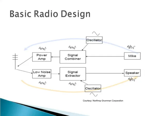
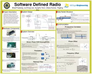
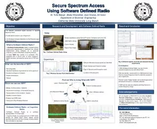
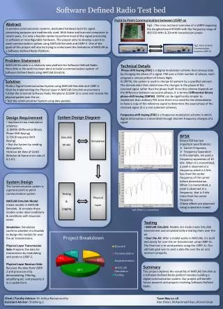
Software Defined Radio Test bed Point to Point Communication between USRP-2s Abstract In wireless communication systems, dedicated hardware built for signal processing purposes are traditionally used. With faster and low-cost computers in recent years, it is now a feasible option to perform most of the signal processing in software or reconfigurable hardware. This project aims to develop a point to point communication system using MATLAB Simulink and USRP-2. One of the goals of this project will also be trying to understand the limitations of MATLAB as a Software Defined Radio Platform. Fig1 : The cross sectional overview of a USRP2 exposing the daughterboard RFX400 with the frequency range of 400-500 MHz & 20+mW transmission power. Fig2: Point to Point Communication between USRP-2s. • Problem Statement • MATLAB Simulink is a relatively new platform for Software Defined Radio. • Very little or No work has been done to build a communication system of Software Defined Radio using MATLAB Simulink. Technical Details Phase-shift keying (PSK) is a digital modulation scheme that conveys data by changing the phase of a signal. PSK uses a finite number of phases, each assigned a unique pattern of binary digits. In DBPSK, the system is used to change bit pattern by a specified amount. The demodulator then determines the changes in the phase of the received signal rather than the phase itself. Since this scheme depends on the difference between successive phases, it is termed Differential binary phase-shift keying (DBPSK). DBPSK can be significantly simpler to implement than ordinary PSK since there is no need for the demodulator to have a copy of the reference signal to determine the exact phase of the received signal (it is a non-coherent scheme). Frequency-shift keying (FSK) is a frequency modulation scheme in which digital information is transmitted through discrete frequency changes of a signal. • Solution • Build a Digital Communication System using MATLAB Simulink and USRP-2. • Start by Implementing the Physical Layer in MATLAB Simulink environment. • Utilize the Universal Software Radio Peripheral 2(USRP-2) to send and receive the physical packet over the air. • Test the communication System using data packets. • Design Requirement • Implement two modulation schemes: • 1) DBPSK (Differential Binary Phase Shift Keying) • 2) FSK (Frequency Shift Keying) • Test the System by sending data packets • Achieve Bit Rate of 50-80 Kbits/sec & frame error rate of 0.1-0.3. System Design Diagram Simulink Model Simulation • BFSK • Binary FSK has two important specifications: • Carrier Frequency • Frequency Separation • In this example, we used a frequency separation of 10 kHz. When 0 is transmitted, a peak is observed at a frequency which is 5 kHz less than the center frequency of the carrier before demodulation. • When 1 is transmitted, a peak is observed at a frequency that is 5 kHz more than the center frequency. • (These effects are observed using a spectrum scope) Fig3: When 0 is transmitted System Design The Communication system is a general point to point communication system. MATLAB Simulink Model: Create models in MATLAB Simulink, & simulate these models under ideal conditions & conditions with Gaussian noise. Simulation: Simulation confirms whether it is feasible to design the models for over the air transmissions. Physical Layer Transmission Side: Prepares the data for transmission by modulating and sends to USRP-2. Physical Layer Receiver Side: Receives the data from USRP-2 and processes it by demodulating, filtering, amplifying etc. and presents it in a usable form. Testing & Logging Physical Layer Fig4: When 1 is transmitted • Testing • MATLAB Simulink: Models are made inside Simulink environment and simulated before testing them over the air. • Over the Air: After a model works in MATLAB, it is built exclusively for over the air transmission using USRP-2s. The final test is to send packets using the USRP-2s. Our ultimate goal was to send a data file over the air and receive it properly. Summary This project explores the versatility of MATLAB Simulink as a Software Defined Radio platform besides building a digital communication system. Our project will benefit future research and projects involving Software Defined Radio. Client / Faculty Advisor: Dr. AdityaRamamoorthy Team May 11-18 Assistant Advisor: Shizheng LiAlex Dolan, Mohammed Khan, AhmetUnsal