Business Process Modeling
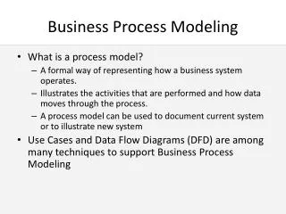
Business Process Modeling. What is a process model? A formal way of representing how a business system operates. Illustrates the activities that are performed and how data moves through the process. A process model can be used to document current system or to illustrate new system

Business Process Modeling
E N D
Presentation Transcript
Business Process Modeling • What is a process model? • A formal way of representing how a business system operates. • Illustrates the activities that are performed and how data moves through the process. • A process model can be used to document current system or to illustrate new system • Use Cases and Data Flow Diagrams (DFD) are among many techniques to support Business Process Modeling
Week 7 Agenda • What’s new in technology? • A couple of ‘Interesting’ Questions • Lecture Material • Data Modeling • Entity-Relationship Diagrams • Normalizing Data • Summary – where we are • NOTE: No tutorials next week (midterm)
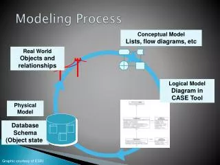
The Systems Development Life Cycle (SDLC) Project Identification & Selection Project Initiation & Planning Process Model Data Structure Logic Modeling Analysis Logical Design Physical Design Implementation Maintenance
Data Modeling Context • DFDs and Logic Modeling • show how, where and when data is used • Data Modeling • shows data definition, structure & relationships • Importance • crucial information for the design phase • data is often more complex than processes • data has reasonably permanent characteristics
Data Models • A data model shows the people, places, and things of interest to an organization and the relationships among them. • The logical data model is an abstraction. Once again, it shows the organization of data without indicating how it is stored, created, or manipulated.
Data Models • A physical data model shows how the data will actually be stored in the database. • Normalization is the process analysts use to check for data redundancy.
Conceptual Data Modeling • What is it? • Captures the structure of organizational data • Is independent of a DBMS or implementation • When is it used? • Conceptual Data Modeling is during analysis • Other data modeling is done throughout SDLC • What form does it take? • Entity Relationship Diagrams (ERDs)
Basic ERD Symbols (IDEF1X) Entity-Name Identifier Attribute-name Attribute-name Attribute-name Relationship-name
A Note • There are several different notations for ERD’s. • none are the de facto standard • we will look at commonalities
Entities • A person, place, object, event or concept that you want to maintain data about • e.g., Customer, Product, Sale, Course, etc. • entities are named with a noun • represented by a rectangle Place Entity Name Here
Figuring Out What Entities to Use • Top Down Modeling • Asking Questions • Determining Business Rules “What things do we care about, in that we need to store them in our data base to perform business operations?” • persons • places • objects • events • concepts
Figuring Out What Entities to Use • Bottom-Up Modeling • looking at forms and reports required in the system • identifying entities from DFD’s
Entity Types and Instances(aka: distinctions modelers make to keep you confused) • Entity Type (or class) refers to a collection of entities that share common properties • e.g. The entity “student” may have two entity types, graduate and undergraduate student • Entity Instance refers to a single unique object within an entity type • e.g., Employee is an entity, customer service representative (CSR) is an entity type, and the CSR named ‘Carl’ is an entity instance.
Attributes A named characteristic of an entity that is of interest to the organization or application e.g., Customer #, Customer Address, etc. Attributes are listed under the entity name attributes are named with nouns Customer C_lastname C_firstname C_telephone
Attributes that are Keys • A key is an attribute that uniquely identifies every instance of an entity type. • Candidate keys are one or more attributes that uniquely identify every entity instance • Primary key - the candidate key that is chosen as the unique identifier for every instance of the entity type. • choose stable, non null, and simple attributes • primary keys are marked with an asterisk in the diagram
Candidate Keys and Identifiers • Title and Copy could uniquely identify a single physical DVD. • It would probably be better to choose a Movie_Serial_Number for each specific DVD so we could keep the key to one attribute (could include mnemonics like the first word and a number:Avengers01)
Relationships • The link that combines entity types. • More formally, a relationship is an association between instances of one or more entity types • labeled with verb phases - one or two • may be represented as a diamond or not shown at all on the diagram to avoid clutter
Relationships • Relationships typically represent a transaction of the organization Rent Members DVDs 1 0 0
Relationship Types: Cardinality One to One One to Many Many to Many Assigned Employee Parking Space 1 1 Owns Student Textbooks 1 N Takes Student Classes N N
Relationship Types: Modality Optional: Rent Members DVDs 1 0 0
More on ERD Concepts • Degrees of Relationships • Cardinality • Many to many relationships
Relationships - Cardinalities The number of instances of entity A that can be associated with instances of entity B For example: Owns Student Textbooks 1 N Cardinalities Takes Student Classes N N
Cardinality - Mandatory The crow’s foot indicates many This line indicates mandatory (at least one must exist) One Many Example: Patient has Patient History Patient Patient History has
Cardinality- Optional The “0” indicates the entity may have zero instances. This means the relation is optional One Many Example: Movie is available on DVD Movie DVD Stored as
Many-to-Many Relationships • Generally implies that there are attributes associated with the relationship • i.e., attributes that do not belong with one of the entities alone but with the combination • Many to Many relationships are very difficult to deal with in databases • A typical approach is to create a 3rd entity when we are faced with a many to many relation • the primary key for the new entity will be the keys of the entities that it connects
Many-to-Many Example 0 Flight books Customer Can be transformed into: Seat 0 Books Is on Flight Customer This transformation makes the relationship easier to handle. In general, we seek to eliminate many to many relationships whenever possible.
Many-to-Many Issues What information does this M-to-M assume is not important to keep track of?
Objectives of Data Modeling • To minimize redundancy of a data base • To completely represent the required data in an information system
Normalizing Data Bases • A set of rules to determine appropriate behavior for a data base. • First, fill in the blanks for EVERY record • Second, remove redundant items (partial dependency) • Third, eliminate complex relations where two or more relational meanings exist (transitive dependency)
Second Normal Form Orders: Ordered Items: Item Descriptions:
Third Normal Form Customers: Orders: City, Province: Ordered Items: Item Descriptions:
Summary • We have covered the Systems Analysis part of the course… • Seek to understand a system, and to start to build a model of that system • Focus on the Systems Development Life Cycle • Process, Data, or Object Oriented • Works with traditional and rapid application development
Summary • We ask questions: • Feasibility • Economic • Technical • Organizational • We plan major steps of the project • Understand current system • Envision possible improvements • automation • process improvement • process reengineering
Summary • We gather data • questionnaires • interviews • observation • JAD • We start to model what we understand to be the processes under study • Build Use Cases • draw DFD’s
Summary • We start to distill the required logic of the process • Logical data flows • Key processes • Logic within the processes themselves • And the data we need to keep within the system • ERD and logical data modeling