Download
1 / 1
10 likes | 115 Vues
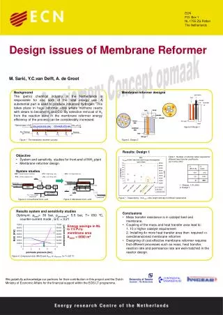
This study focuses on the design challenges in membrane reformer units used for hydrogen production in the (petro)chemical industry in the Netherlands. It explores the energy efficiency improvement by selectively removing H2 in the reaction zone using membranes, with a detailed analysis of different designs and system studies. The research reveals the importance of matching mass transfer, heat transfer, reaction rate, and permeance rate for optimal membrane reformer performance.

E N D
ECN P.O. Box 1 NL 1755 ZG Petten The Netherlands Design issues of Membrane Reformer M. Sarić, Y.C.van Delft, A. de Groot Background The (petro) chemical industry in the Netherlands is responsible for one sixth of the total energy use. A substantial part is used to produce industrial hydrogen. This takes place in huge reformer units where methane reacts with steam to become H2 and CO. By selective removal of H2 from the reaction zone in the membrane reformer energy efficiency of the process can be considerably increased. Membrane reformer designs Figure 5 Design 1 Figure 1 The membrane reformer concept Figure 6. Design 2 • Objective • System and sensitivity studies for front-end of NH3 plant • Membrane reformer design • System studies Results: Design 1 Table 1. Number of reformer tubes required for different heat transfer coefficients (dt=11cm,L=9m) 1 –Branan, C.R.,2002 2- Design 1 Figure 7. Dependency of Amem ,tube lenght and Δp on different parameters Figure 3. Membrane front –end Figure 2. Conventional front –end Results system and sensitivity studies Optimum: pfeed= 30 bar, ppermeate= 5.5 bar, T= 650 ºC, counter-current mode , S/C = 3.21 Energy savings in NL is 7.5 PJ/y. membrane area Amem = 6000 m2 • Conclusions • Mass transfer resistance is in catalyst bed and membrane. • Coupling of the mass and heat transfer area lead to: • 1. 10 x higher catalyst requirement • 2. Installing 4x more heat transfer area then required => overdimensioned membrane reformer • Designing of cost effective membrane reformer requires that different processes such as mass, heat transfer, reaction rate and permeance rate are well-matched in the reactor design. Figure 4. Compressor duty (MUG) and Amem vs. ppermeate for T= 600 ºC We gratefully acknowledge our partners for their contribution in this project and the Dutch Ministry of Economic Affairs for the financial support within the EOS LT programme.