Hydrogen Membrane Reformer Technology
50 likes | 87 Vues
Explore the innovative Hydrogen Membrane Reformer Technology that efficiently extracts hydrogen from reactors, drives reactions, and widens temperature ranges for syngas production in power plants.

Hydrogen Membrane Reformer Technology
E N D
Presentation Transcript
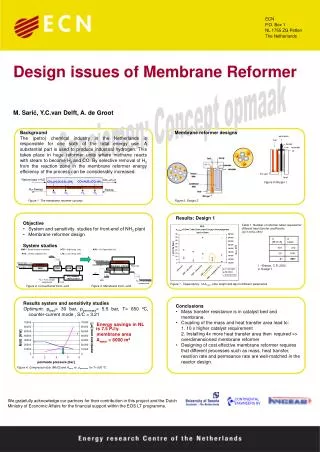
Hydrogen Membrane Reformer Technology 6.11.2003
PH2(I) PH2(II) e- ½ H2 ½ H2 H+ (Syngas) (Hydrogen) ½ H2 H+ + e- H+ + e- ½ H2 PH2(I) > PH2(II) • Driving force for H2: H2 flux ≈log PH2(I) / PH2(II) • Membrane material 100% dense Hydrogen Mixed Conducting Membranes
Hydrogen Membrane Reformer • extract product gas (H2) from reactor • drive equilibrium limited reactions towards completion • expand allowed range of temperatures and pressures
Air CC Air/H2O ½ O2+H2 = H2O Sweep 1 3 CH4+H2O = CO+3H2 CO +H2O = CO2+H2 CH4+H2O = CO+3H2 CO +H2O = CO2+H2 2 4 H2 Generator System step 1 & 2 H2membrane H2membrane N2+H2O (Sweep) 1 3 N2+H2O+H2 Air Q Q CH4 / H2O Residual Gas Syngas H2 H2 H2 H2 4 2