NETWORKING MEDIA
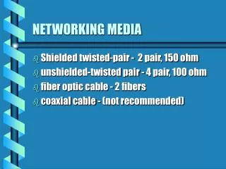
NETWORKING MEDIA. Shielded twisted-pair - 2 pair, 150 ohm unshielded-twisted pair - 4 pair, 100 ohm fiber optic cable - 2 fibers coaxial cable - (not recommended). Shielded Twisted Pair Provides resistance to EMI and radio frequency Cancellation and twisting of wires, shielding

NETWORKING MEDIA
E N D
Presentation Transcript
NETWORKING MEDIA • Shielded twisted-pair - 2 pair, 150 ohm • unshielded-twisted pair - 4 pair, 100 ohm • fiber optic cable - 2 fibers • coaxial cable - (not recommended)
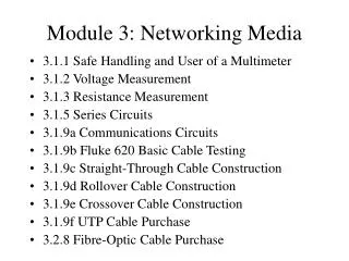
Shielded Twisted Pair Provides resistance to EMI and radio frequency Cancellation and twisting of wires, shielding More expensive Cable length 100m Unshielded twisted-pair relies on cancellation effect number of twists varies Less expensive Cable length 100m Fastest copper based media today Twisted Pair Cabling
COAXIAL CABLE • Copper conductor in center • Flexible insulation • Metallic foil or copper braid acts as second wire in circuit • Max. length 500m • Thicker than Twisted pair, more difficult to work with
FIBER OPTIC CABLE • Not susceptible to EMI • Higher data rates than any other media • Each optical fiber is surrounded by layers of plastic such as Kevlar, and an outer jacket • Max. cable length up to 2km • Most expensive
TIA/EIA STANDARDS • Horizontal cabling • telecommunications closets • backbone cabling • equipment rooms • work areas • entrance facilities
Cabling • Crossover Cable - used to connect one device to another • Straight through - used to connect to hub or patch panel • Rollover or console cable - used to connect a PC to the router for purposes of accessing the router
10BASE-T • Cat 5 twisted pair • Terminated with RJ-45 • Layer 1 device • Carries bits
Patch Panel • Groups of Rj-45 (12, 24, 48) PORTS • Rack mounted • Front sides RJ-45 jacks • Back sides punch-down Blocks • Layer 1 device
Repeater • Regenerates and retime signals • Enables cables to extend farther to reach longer distances • Deal with packets at bit level (1) • Increase number of nodes that can be connected to a network • Cannot filter traffic
Multiport Repeaters (Hubs) • Regenerate, amplify and retime signals • Deal only with bits • Layer 1 device
COLLISIONS • If more than one node attempts to transmit at the same time • Packets destroyed, bit by bit • Two devices trying to occupy the same medium (wire) at the same time
COLLISION DOMAIN • Repeaters and hubs extend the collision domain • Ethernet rule of thumb 5-4-3-2-1 rule. Five sections of network, four repeaters or hubs, three sections of the network are mixing segments, two sections are link segments, and one large collision domain
SEGMENTATION • Reduces size of collision domain • Networking device used are bridges, switches and routers • Eliminate unnecessary traffic on busy network by dividing into segments and filtering traffic based on station address
Bus Topology • All nodes connected directly to one line • Wired to a common wire • Disadvantage - break in cable disconnects host from each other
RING TOPOLOGY • Single closed ring consisting of nodes and links • Connected to only two adjacent nodes • Each station must pass info to adjacent station
DUAL RING • Two concentric rings, each linked only to its adjacent ring neighbor, not connected • Each network device is part of two independent ring topologies • Acts like two independent rings, only one at a time is used.
STAR TOPOLOGY • Has a central node with all links radiating from it • Allows all other nodes to communicate with each other • If central node fails, whole network is disconnected. • Info goes through one device
EXTENDED START TOPOLOGY • Repeats a star topology, except each node that links to the central node is the center of another star • Has a core star topology • Each end node of core topology acts as the center of its own star topology • Keeps wiring run shorter • Hierarchical, info encouraged to stay local
COMPLETE (MESH) TOPOLOGY • Every node is physically connected to each other node • Information can flow if one link goes down • Disadvantage is for anything more than a small number of nodes the amount of media is overwhelming