Download

1 / 45
450 likes | 586 Vues
Introduction to the Murchison Widefield Array Project Alan R. Whitney MIT Haystack Observatory. Outline. The genesis The process of defining the project A glimpse of the science objectives Challenges to be overcome A feel for what all is involved Some results from early deployment studies.

E N D
Introduction to the Murchison Widefield Array ProjectAlan R. WhitneyMIT Haystack Observatory
Outline The genesis The process of defining the project A glimpse of the science objectives Challenges to be overcome A feel for what all is involved Some results from early deployment studies
Mid-late 1990s - Haystack was looking to get into arrays Low frequency arrays presented the most exciting opportunity Unexplored territory Exciting science Digital telescopes - rapidly becoming technologically feasible Affordable hardware The Genesis
The key science objectives Epoch of Reionization Power spectrum Strömgren spheres Solar/Heliospheric Faraday rotation, B-field Interplanetary Scintillation (IPS) Solar burst imaging Transients Deep blind survey Other Pulsars ISM survey Recombination lines Etc. • Frequency range • Collecting area • Array configuration • Bandwidth • Frequency resolution • Time resolution • Location • Technological feasibility • Computational feasibility • Available knowhow • Calibration requirements • Data analysis and processing approach • Logisitics
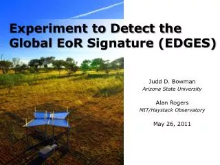
The Epoch of Re-Ionization • ~300,000 years after Big Bang, hydrogen formed (opaque) • After ~1 billion years hydrogen is ionized by stars (transparent) • In between are the dark ages • The MWA can see through the hydrogen
Cosmic Re-ionization Nick Gnedin
The Sun-Earth Connection Travel Time = 2 - 4 Days Magnetopause Bow Shock CME Solar Wind Direction
Radiation Hazards Communications Failures Damage to Satellites GPS Navigation Problems The need for predicting Space Weather Geomagnetic Storms Disrupt Technological Systems
Direct Imaging of CMEs CMEs also visible directly Synchrotron emission Polarimetry yields transverse B-field information Complementary to IPS data Faraday rotation measurements Measure longitudinal B-field Complete characterization of particles and field …
Principle of Faraday Rotation = 2cneB.ds = 2 RM For a rotation measure of 1 rad m-2 = 1° at 2.3 GHz (=0.13 m) = 90° at 240 MHz (=1.25 m) = 530° at 100 MHz (=3.00 m) Observe a known linearly polarised background source through the magneto-ionic medium and use the observed changes in plane of polarisation to model the medium
The origin of IPS Plane wavefront incident from a distant compact source The density fluctuations in the Solar Wind act like a medium with fluctuating refractive index, leading to corrugations in the emerging wavefront These phase fluctuations develop into intensity fluctuations by the time they reach the observer The resulting interference pattern sweeps past the telescope, leading to IPS
What transient sources might we find? Many rare giant pulsar pulses (2 now known) Radio bursts from cosmic ray neutrinos hitting the Moon Bright stellar radio flares Gamma ray burst afterglows Microlensing events involving AGNs Coherent burst emission from magnetar glitches Black hole/neutron star in-spiral events Coherent burst emission from planets and extra-solar planets Many unsuspected phenomena?
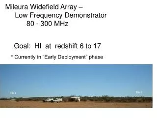
The MWA – a state of the art instrument • Major new instrument to explore the low end of the radio-frequency spectrum 80-300 MHz • Being developed by Haystack scientists and engineers with collaborators • Fully digital; no moving parts • Situated in Western Australia – because of low RFI environment Depends on massive computing power –largely a “software telescope”
Image Creation • Real-time imaging supercomputer must absorb and process up to 160 Gbps continuously from the correlator to create a new calibrated high-resolution sky image every 8 seconds! • Thousands of foreground stars and galaxies must be accurately substracted from these images to reveal the target background radiation • These foreground-subtracteded images form the primary dataset for a large fraction of MWA science goals
Implementation Phases • 32-tile system (32T) • Conceived as engineering test bed • Evolved into validation platform for MWA technologies • Successful ly completed and tested in 2009-2010 • 512-tile system (512T) • Scoped for calibratability and key science capability • Additional development required (software + firmware) • Buildout to 128T currently in progress; budget limitations are delaying buildout to 512T
The MWA site – The Shire of Murchison
Challenges Calibration of ionospheric effects Foreground subtraction for EoR analysis High dynamic range wide field of view imaging
Solar Burst Activity Single baseline, amplitude vs freq and time 20 ~1 min x 4 MHz strips over 1 hour period
The Big Challenges: Multiple simultaneous technical innovations This is new ground, in many different ways Short timescale Driven by political and financial necessity Distributed project team Physical distance and timezones Cultural differences, some subtle
Summary MWA is a major technical innovation to enable exploration of a new frequency regime with major new capabilities; first real-time imaging array, made possible by massive computing power Risks are high, but potential payoffs also high 32T system has proven major parts of MWA concept, but 512T system needed to verify some aspects of design, particularly calibration 128T buildout currently in progress; full 512T system will require significant new funding that NSF is presently unable to provide As a pathfinder for SKA, a successful MWA is a critical steppingstone to HERA2 and the SKA array