Download

1 / 61
610 likes | 841 Vues
Vortex Flow, LLC Customer Presentation February, 2004. A technology tornado is here!. Presentation Agenda. Vortex Theory Vortex DX Tools Vortex DX Lab Testing Vortex DX Tools Field Results How to Apply DX Tools to your Operations Vortex SX Tools theory Vortex SX Tools Field Results

E N D
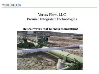
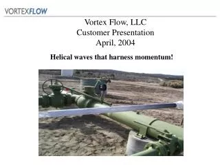
Vortex Flow, LLCCustomer PresentationFebruary, 2004 A technology tornado is here!
Presentation Agenda • Vortex Theory • Vortex DX Tools • Vortex DX Lab Testing • Vortex DX Tools Field Results • How to Apply DX Tools to your Operations • Vortex SX Tools theory • Vortex SX Tools Field Results • How to Apply SX Tools to your Operations?
Vortex Flow, LLC Providing Breakthrough Oilfield Products
Vortex Theory * • People have been studying rotational flow since the 1800’s • Simply put, • They want to know how nature gets from this • To this • The Coriolis effect doesn’t have the horsepower to transfer enough energy fast enough to explain it
Vortex Theory * • Hurricanes last for weeks • Tornadoes last for hours • If a man-made vortex can be controlled to last for 10-15 minutes it could be valuable • Typical velocities in gas flow are around 20-40 ft/sec • 10 minutes at 20 ft/sec = 2.2 miles • 15 minutes at 40 ft/sec = 6.8 miles
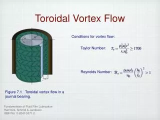
Vortex Tool Physics Discussion • “As a stream of gases and liquids enters the Vortex tool it is forced by a “bluff body” in the flow stream to spin rapidly. The high angular acceleration slings the heavier liquid toward the pipe wall. As this spinning flow moves up the tool, the configuration of the tool allows the spin angle to relax to a very efficient value. This efficient helix-angle will propagate very long distances. The consequence of the liquid moving like the rifling on a gun barrel is that the no-flow boundary at the edge of the central gas flow is moving—resulting in a lower differential velocity between the bulk flow and the outer edge of the flow, which yields a lower shear force and a lower pressure drop due to friction. A second benefit is provided by eliminating the “slip” between liquid droplets in the flow and the gas stream. Removing this slip force reduces the amount of work the gas must do as it moves reducing the total pressure drop.” • David Simpson, MuleShoe Engineering
CHANGING THE FLOW PATTERN Mingaleeva in her paper “On the Mechanism of a Helical Motion of Fluids in Regions of Sharp Path Bending” determined that, “ The path of least resistance for liquid and gases is determined to be of a helicaltrajectory, and that the slope of the helix varies within 45-65o from the horizontal. The helical path was more favorable from an energy utilization viewpoint, as the power spent to overcome the hydraulic drag for raising an air column, as compared to the motion and rising of equivalent air mass at the same velocities by a straight column is significantly lower.”
Advanced Fluid Movement and Pressure Reduction Technology! Vortex Flow – DX Downhole Tools • Revolutionary flow development chamber for oil and gas wells • Reduces flowing bottom-hole pressure • Extends Well flowing lifespan • Removes Liquids from Wellbore • Reduces friction and turbulence by organizing multi-phase flow • Even Mitigates paraffin build-up • Proven to consistently enhance oil and gas production!
LAB TESTING CONCLUSIONS • DX tools successfully reduces liquid loading, • Consistent results at varying pressures • The tool lowered critical velocity • Testing program allowed improvements in tool design to be evaluated. • Potential use in, • Avoiding liquid-loading in flowing wells • Replacing pumping equipment • Replacing plunger systems • Improving flow in horizontal wells • Being A slug stabilizer by reducing slug sizes • Reducing gas requirements in artificial gas lift
A&M Field - Wellbore Testing • Texas A&M Field Testing – Downhole VX Removes Water from Wellbore – 1,200’ wellbore. The downhole VX was able to lift the water with only 56% of the critical rate up the 2 3/8 tubing... • Accepted industry liquid lifting theory shows that for a wellhead pressure of 20 psig (34.7 psia), and 2 3/8 tubing, the Turner equation gives a minimum lift velocity of 49 ft/sec which corresponds to a flow rate of 0.201 MMSCFD which is equal to 0.162 lb/sec mass rate.During Texas A&M testing, 10 gallons of water was injected and .09 lb/sec was the minimum mass flow rate with which the well would unload. This mass flow rate corresponds to approximately 0.11 MMSCFD and a minimum lift velocity of 26.72 ft/sec.
Advanced Fluid Movement and Pressure Reduction Technology! Downhole VX Installations Vortex Downhole DX Field Installations Customer Results
Vortex DX TOOLS CBM Installation for Marathon Barnett Shale Installation forDevon
Downhole Applications Downhole DX – Pressure Gradient Comparison Reduced Fluid Level PRE POST
Downhole Applications Impact on Production of Lower Fluid Level Improved Production
Vortex DX Field Performance • Organizes multi-phase flow at the bottom of the wellbore • This flow organization at the most difficult point to lift liquids can improve liquid lifting capacity on even very deep wells. • Lowers flowing bottom hole pressure • Lifts more water with same gas rate • Can lift water with as little as 56% of calculated gas rate
Some Field Lessons Learned • Large ‘phase change’ occurring up the tubing can increase the gas rate needed to keep the well unloaded • We’re developing a mid-hole tool to address this • Reservoir pressure is a key variable in evaluating very low GOR installations. • Centralizers are effective for our side-port tools • Packers are not required • The DX tools can even make intermitted wells more effective – even if not fully flowing
Vortex DX Tool Operating Parameters? • Can flow up to 266 BWD with only 90 MCFD • Can improve flow up to 12,000’ deep • Can lift water with as little as 56% of calculated gas rate • Can improve production by lowering bottom hole flowing pressure in a steady flowing wellbore! • DX tools are made with no moving parts
Free-flowing Well Extended Free-flow Period Delay Need for Artificial Lift Advanced Fluid Movement and Pressure Reduction Technology! Downhole DX DX is Only Tool that Enhances Flowing Production from Day One! 75% of Critical 50% of Critical
Just out – Insert style Vortex tool! • Eliminates need to pull tubing to install. • Eliminates killing well, can run live on slickline • Set in PN, SN, or collar/tubing stop. Retrieved via slickline, similar to bumper spring assembly. • Can be run above bumper spring to enhance plunger lift operation. • Can be run above gas lift mandrel to improve gas lift performance and use less makeup gas. • Bottom line: less risk, less downtime, less $
When is the Best Time to Install a Vortex DX tool? • Upon completion of a new well • Lowers flowing bottom-hole pressure from the start of production • Lifts additional water from the wellbore • More quickly dewaters newly fractured wells • May increase drainage area • Extends a well’s flowing life 25% below the critical gas rate
Please Complete Vortex DX well Data Sheets for Your Installation Opportunitieswww.vortexflowllc.com
Advanced Fluid Movement and Pressure Reduction Technology! Vortex Flow – SX Surface Tools • Revolutionary flow development chamber for oil and gas operations. • Moves Liquids • Stagnant in flowlines and gathering lines • Reduces line freeze – ups • Reduces line pigging • Reduces friction • Reduces turbulence - organizes multi-phase flow • Mitigates paraffin build-up • Eliminates gas pockets in water lines • Proven to consistently enhance oil and gas production!
Water in Piping * • Design piping for: • Maximum velocity about 100 ft/sec (minimize wasted hp). • Minimum velocity 36 ft/sec (keep water mobile). • Piping too big leaves water behind.
Advanced Fluid Movement and Pressure Reduction Technology! Production Quantity = Permeability * (Reservoir Pressure – Downhole Pressure) Bottom Hole Pressure = Surface Pressure + Friction + Head Separator/Dehydrator Wellhead Ground Level ‘Pre Vortex’ Flowline Pressure at wellhead = 200 psi ‘Pre Vortex’ Gathering Line Pressure after Separator/Dehydrator = 128 psi Reservoir Pressure 800 psi ‘Pre-Vortex’ Bottom Hole Pressure = 700 psi Figure 2
Advanced Fluid Movement and Pressure Reduction Technology! Vortex Reduces Flowline Friction/Surface Pressure – Indirectly Reduces Bottom Hole Pressure Separator/Dehydrator Wellhead Ground Level ‘Pre Vortex’ Gathering Line Pressure after Separator/Dehydrator = 128 psi ‘Post Vortex’ Flowline Pressure at wellhead = 130 psi Reservoir Pressure 800 psi ‘Post-Vortex Flowline’ Bottom Hole Pressure = 630 psi Figure 2
Advanced Fluid Movement and Pressure Reduction Technology! Vortex Reduces Friction in Gathering Line – Further Reduction in Surface Pressure and Bottom Hole Pressure Separator/Dehydrator Wellhead Ground Level ‘Pre Vortex’ Gathering Line Pressure after Separator/Dehydrator = 98 psi ‘Post Vortex’ Flowline Pressure at wellhead = 100 psi Reservoir Pressure 800 psi ‘Post-Vortex Flowline’ Bottom Hole Pressure = 600 psi Figure 3
Advanced Fluid Movement and Pressure Reduction Technology! Modeled Production Increase • Reduced Bottom Hole Pressure from 87.5% to 82.5% means moving from 20% to 35% of the maximum rate = • a 75% increase in Production! Moving up the Production Curve
Advanced Pressure Reduction Technology! Pre-Vortex VX Install - Oil Production Improved Production
Advanced Pressure Reduction Technology! Post Vortex VX Install - Oil Production Improved Production
Flowline Applications 1,200’, Multi-Phase, Flowline Installation Production Improved
Flowline Applications 700’, Multi-Phase, Flowline Installations Production Improved
Advanced Fluid Movement and Pressure Reduction Technology! DOE Field Tests - RMOTC • Paraffin Mitigation field tests were initiated at the Rocky Mountain Oilfield Testing Center in December of ‘02. • Test results show a remarkable reduction paraffin accumulation! • Flowline would typically require ‘hot water’ treatment every 30 days – only two treatments required in past 13 months! Both treatments were after a chemical treatment downhole. • Second test has had no treatments for over seven months. Further Detailed DOE Testing shows paraffin mitigation
Advanced Fluid Movement and Pressure Reduction Technology! RMOTC flow line clogged with Paraffin This picture represents the flow line after 30 days of production.
Advanced Fluid Movement and Pressure Reduction Technology! Paraffin Prone Flowline Now with the Vortex SX April, 2003
Pigging Eliminated • Duke Energy used the Vortex SX in an attempt to eliminate pigging on a 3” lateral in a gathering system in the DJ basin. The 3 mile line was on a schedule that required pigging every week to remove accumulated fluids in the line. This line would also occasionally freeze-up during winter • The Vortex SX was installed in approximately 3 hours on September 5, 2002. In the 15 months following installation, there have been two very impressive benefits: • The first thing noted by the local pumper was that line pressure fell by 16%, from 240 psi to 200 psi • In the 15 months since the tool has been operating, the line has not required pigging, reducing pigging expense and improving line uptime and related line throughput!
Advanced Fluid Movement and Pressure Reduction Technology! • San Juan Basin Installations Customer Results
Gathering Applications SX Installation Replaces Pigging Pigging Replaced
Advanced Fluid Movement and Pressure Reduction Technology! Field Experience “We had a two mile, 4” flowline that produced 6 BWD, 70 BOD, and 1,100 MCFD. This line did not have any drips in place. We had to regularly pig this line as wellhead pressure would increase from 600 PSI to 800 PSI in only a couple of days. The liquid holdup would also cause this line to freeze often in the winter. We installed a 4” Vortex surface VX tool in place of our pig launcher on September 3rd, 2003. On the day of installation we pigged the line prior to installing the VX tool. The next day we had a slug of fluid in the treating vessels. The VX tool has eliminated our need to pig this line while enabling our wellhead pressure to be consistently only 500 PSI. This has reduced our average wellhead pressure by 100 PSI and eliminated our costs for pigging. We have also noticed less slugging of fluid and gas at the treating facility. We can’t wait to make it through the winter without our line freezing.” Michael Tornes Lario Oil and Gas Company Wyoming September 23, 2003