Vacuum Technology for Accelerators: Key Components and Maintenance
520 likes | 545 Vues
Learn about vacuum levels, materials, cleaning, seals, pumps, and NEG coatings crucial for maintaining proper vacuum in accelerator systems to avoid beam loss and improve beam lifetime.

Vacuum Technology for Accelerators: Key Components and Maintenance
E N D
Presentation Transcript
Vacuum & Surface ScienceLecture 17 Sunil Patel Vacuum Section Leader www.isis.stfc.ac.uk Sunil.Patel@stfc.ac.uk
Part 1 – Vacuum for Accelerators Part 2 – Surface Science
Part 1 - Vacuum for Accelerators • In the UK – ISIS, Diamond, CLARA • Also – CERN, ESRF, SNS, SOLEIL, ELLECTRA, DESY, BESSY etc
Part 1 - Vacuum for Accelerators The Vacuum Spectrum
Part 1 - Vacuum for Accelerators In general the vacuum level required for an accelerator is determined by its operation. • Single pass – 1 to 1000µs (10-7 to10-9mbar) OR • Storage ring – 10 hours or more (10-9mbar or less)
Part 1 - Vacuum for Accelerators So what happens if you fail to achieve the required vacuum level ? • Beam scattering occurs – increased radiation levels • Beam shape changes • Beam lifetime reduced • Beam Loss Occurs
Part 1 - Vacuum for Accelerators How to ensure you achieve the required vacuum level and avoid beam loss. • Correct selection of materials for the external vacuum vessel and also components used internally (including surface finish). • Ensure that vacuum vessels and components are kept clean to reduce outgassing and desorption effects. • Adequate pumping, leak testing and conditioning.
Part 1 - Vacuum for Accelerators Any accelerator vacuum system needs the following ingredients; • Vacuum Vessel • Internal vacuum components (eg. beam monitors) • Cleaning procedure for vessel and components • Vacuum Seals & Clamps • Gate valves – RF screened if necessary • Pumps and Gauges • Residual Gas Analyser (RGA’s) • Modelling software • Control system
Part 1 - Vacuum for Accelerators The Vacuum Vessel – Common Materials • Stainless steel (grades 304L or 316L and N) • Most grades of Aluminium • Titanium • Copper • Ceramic
Part 1 - Vacuum for Accelerators 1 of 10 Ceramic vacuum vessel used on ISIS, 4m long, 19 segments
Part 1 - Vacuum for Accelerators Materials for internal vacuum components • Aluminium • Oxygen Free Copper • Stainless Steel • Glidcop (Copper and Aluminium oxide alloy) • Gold • Silica Avoid materials containing brass or cadmium and PVC insulated wire
Part 1 - Vacuum for Accelerators Cleaning of vacuum vessel and components • Cleaning procedures will help to reduce thermal outgassing and also electron, photon and ion desorption, but difficult to stop these completely. • Typically cleaning involves washing the vessel or component in solvent, then drying following by baking to remove solvent residue.
Part 1 - Vacuum for Accelerators • Most accelerators will have an on-site cleaning facility – solvent baths and ovens
Part 1 - Vacuum for Accelerators Vacuum Seals – Usually soft metals that are easily squashed (avoid elastomers eg. Viton) • Copper • Aluminium • Gold • Indium
Part 1 - Vacuum for Accelerators Vacuum Clamps – depends on flange dimensions • Conflat • ISO • Quick Release • Remote operation for high radiation areas.
Part 1 - Vacuum for Accelerators Vacuum Valves – RF Screened (springy fingers and Fast Closing
Part 1 - Vacuum for Accelerators Minimising beam disturbance – more examples of screening
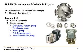
Part 1 - Vacuum for Accelerators Types of Vacuum Pump
Part 1 - Vacuum for Accelerators Vacuum Pumps – Ion Pumps (Diode or Triode) (From 0.2 l/s to 500 l/s) Operation based on the penning discharge (HV applied in presence of a strong magnetic field). Cathode bombarded resulting in sputtering and trapping in or on the surface.
Part 1 - Vacuum for Accelerators Getter pumps - Titanium Sublimation (TSP) and Non Evaporable Getter (NEG) TSP – Evaporates titanium over nearby surfaces. “Trapping effect” can be improved by cooling.
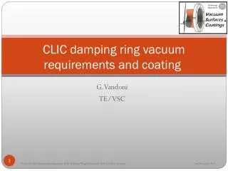
Part 1 - Vacuum for Accelerators “NEG coatings are thin films, of getter material, which once activated has the ability to pump a vacuum vessel. It can also minimise outgassing and secondary electron yield from the internal surface of the vessel”. Typically activation temperature is between 150 and 400ºC. Extensive research carried out at CERN by Cristoforo Benvenuti
Part 1 - Vacuum for Accelerators • Helps to improve the base pressure in the accelerator or vacuum vessel, which improves beam-lifetime. • Helps to reduce outgassing and secondary electron yield from the vessel walls, which also improves beam-lifetime. • Modern insertion devices have limited conductance for pumping by conventional means.
Part 1 - Vacuum for Accelerators What are NEG coatings made from? • Preference for elements that have high oxygen diffusion and solubility limits. Hence mainly elements in Group 4 and 5 of the periodic table (i.e. Ti, Zr, Hf, V, Nb and Ta). • Usually binary (e.g. TiV), or tertiary alloys of the above used (e.g. TiVZr or TiVHf).
Part 1 - Vacuum for Accelerators What makes a good NEG coating • Good adhesion • Low activation temperature • High solubility and diffusion limit for oxygen • High mechanical resistance • Large pumping speeds • Low photoelectron and secondary electron yields • Non toxic
Part 1 - Vacuum for Accelerators How do they work ? • X-ray Photoelectron Spectroscopy shows that during activation surface composition changes from being oxygen rich to more metallic in nature. This provides active sites for adsorption. • H2 is adsorbed reversibly and can easily be removed by re-heated. • CO and CO2 are adsorbed irreversibly forming stable compounds with the NEG alloy such as titanium oxide. When heated these compounds migrate into the bulk of the material leaving new sites for adsorption.
Part 1 - Vacuum for Accelerators What are the other benefits of using NEG coatings? • When used in conjunction with ion and turbo pumps can help to attain extreme high vacuum conditions (XHV), by removal of CO, H2 and CO2. • Vibration free, suitable for very delicate experiments. • Not influenced by magnetic or electric fields.
Part 1 - Vacuum for Accelerators What about the disadvantages of NEG • Expect to pay more for a NEG coated vessel than a uncoated one. • Risk of contamination or poisoning during the activation process and during bakeout which will reduce the lifetime of the coating. • Not suitable for pumping noble gases e.g. methane and argon • Should never be exposed to high concentrations of hydrogen.
Part 1 - Vacuum for Accelerators Options for adding NEG coatings • Install cartridge with the getter material on it, e.g. SAES ST101 and ST707.
Part 1 - Vacuum for Accelerators • Anti-chamber arrangement • Vacuum coat the inside of the vessel typically using magnetron sputtering.
Part 1 - Vacuum for Accelerators Vacuum gauges – no one gauge covers the entire vacuum spectrum.
Part 1 - Vacuum for Accelerators IMG – operation based on a penning discharge in the presence of a magnetic field. Gas ionization used to Measure pressure. Gauge is gas sensitive due to ionization probabilities. Can be difficult to initiate discharge at low pressures
Part 1 - Vacuum for Accelerators RGA’s – for diagnostics and leak testing
Part 1 - Vacuum for Accelerators Modelling software for accelerators • Basic (Diffusion) Model – whilst quick and easy struggles with complicated vessel shapes. • Better option is to use 3D test particle Monte-Carlo simulation eg. Molflow (R. Kersevan, CERN).
Part 1 - Vacuum for Accelerators The Vacuum Control System • LabView • EPICS • Device Net • Profibus
Part 1 - Vacuum for Accelerators Electron Cloud Effect Beam losses occur as a results of bunches of positively charged particles interacting with stray electrons from residual gases or photoemission (electrons emitted from the beampipe wall). The cascade of electrons created results in the bunches being surround by a cloud of electrons that cause head-tail instability.
Part 1 - Vacuum for Accelerators Can be reduced by treating the internal surface of the vacuum vessel with a coating eg. Titanium or Titanium Nitride, NEG or Carbon, which reduce secondary electron yield. Or Apply an external field using a solenoid coil around the beampipe to keep stray electrons nearer the wall.
Part 1 - Vacuum for Accelerators How has the design of accelerator vacuum systems changed over last 10 to 15 years? • Control system and modelling system developments • Vacuum modules (girders) • Decommissioning costs need to be taken into consideration.
Part 2 – Surface Science • Extensively used for studying catalysts, semiconductor and coatings. • Need vacuum to eliminate gas scattering effects and maintain a clean surface for analysis. • Basically for monolayer coverage
Part 2 – Surface Science Some surface science techniques – no one method is the best
Part 2 – Surface Science Auger Electron Spectroscopy • Elemental analysis of top 2nm of surface. • Bombarding sample with a primary electron beam. This results in removal of an inner (K) shell electron and emission of an Auger electron. • Use hemispherical analyser to analyse Auger electrons. • Scanning Auger involves rastering beam over surface to build up an image
Part 2 – Surface Science Photoelectron Spectroscopy (PES) • X-rays (XPS) photon energy of 200 - 2000eV (core level analysis) or Ultraviolet (UPS) photon energy 10 – 45eV (valence bands) • Need a monochromatic source of x-rays (X-ray gun), helium lamp or a synchrotron • Like AES measure kinetic energy of emitted electron based on the following equation KE = hv – BE (Binding Energy) • Each element has a characteristic binding energy, peak intensity indicates concentration.
Part 2 – Surface Science • Chemical shifts can be used to identify different oxidation states • Angle dependent analysis can also be carried out by measuring the photoelectrons emitted at different angles
Part 2 – Surface Science Secondary Ion Mass Spectrometry (SIMS) • Sample bombarded with high energy ions (eg Ar+), resulting in the emission of neutral and charged species that are then analysed using a mass spectrometer. • Can carry out depth analysis of surface. • Mass spectrometer could be quadrupole, magnetic sector or time of flight.
Part 2 – Surface Science SIMS analysis of PTFE
Part 2 – Surface Science Scanning Tunnelling Microscopy (STM) • Requires a sharp tip (probe) – single atom for best resolution. Can be carried out at room or low temperatures. • Normally the tunnelling current is kept constant whilst the tip moves along the surface. This results in an image of the surface.