Download
1 / 32
330 likes | 491 Vues
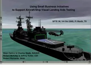
Using Small Business Initiatives to Support Aircraft/Ship Visual Landing Aids Testing. SFTE 36, 3-6 Oct 2005, Ft Worth, TX. Dean Carico & Charles Slade, NAVAIR Robert McKillip & Jeffrey Keller, CDI Robert Richards, SHAI. Background. Increased night helo/ship operations during Korean War

E N D
Using Small Business Initiatives to Support Aircraft/Ship Visual Landing Aids Testing SFTE 36, 3-6 Oct 2005, Ft Worth, TX Dean Carico & Charles Slade, NAVAIR Robert McKillip & Jeffrey Keller, CDI Robert Richards, SHAI
Background • Increased night helo/ship operations during Korean War • Operational VLA testing during 1960’s and early 1970’s • General Services Bulletins initiated during 1960’s • Shore and ship-based developmental testing early 1970’s • SH-2F LAMPS MK I during the 1970’s • SH-60B LAMPS MK III during the 1980’s • SH-60F/NVD shipboard testing during 1990’s • Remote source fiber optic ship lighting testing in 1999 • Several new upcoming ship programs: DD(X), LCS, etc • PC-based VLA Test Tool SBIR topic approved in 2003 • Continuum Dynamics, Inc. of Ewing, NJ • Stottler Henke & Associates, Inc of San Mateo, CA
Goals of CDI Development Effort • Demonstrate accurate VLA visual reconstruction using PC hardware and software • Create, demonstrate and evaluate user-friendly VLA concept geometry re-creation tools • Create an extensive suite of VLA concept test and evaluation tools (guided by Navy input) • Provide functional software development methodology for design and implementation, testing, and lifecycle support • Show methods for extending these tools to additional applications and uses (e.g., manned simulation or test planning)
Why VRML/X3D? • VRML97 and X3D are scene description standards • Represent visual scene in a tree-structured set of nodes • VRML files are ASCII text; X3D is XML-like • Animation features and time-driven execution are included • Extendable through “script” nodes that permit Java or Javascript program control of node “input” and “output” • Operates as “plug-in” companion-ware to web browsers • VRML/X3D nodes represent many of the same 3D graphics primitives as general-purpose graphics libraries (e.g., OpenGL) • Java interface allows for graphics content and features to be modified as a function of viewer position and viewing direction within a scene • Permits accurate modeling of optical features of VLA device • Allows for accommodation of known PC graphics limitations
Graphics Software Structure • Screen visuals are generated through a series of software layers vs. direct hardware programming via specialized libraries • VRML browser plug-ins have been optimized to provide nearly equivalent performance, with a much friendlier, non-proprietary interface Java Classes JavaScript Files VRML Files (*.wrl) VRML Plug-In HTML Browser Java VM Operating System Graphics Hardware
Routing Diagram Scene Node Tree Diagram Java Extendability of VRML • VRML is a node-centered scene graph description, with an “event chain” controlled through ROUTEs of input and output node information • Java provides added software functions within a SCRIPT node that can act on this ROUTE information
VLA Re-creation Toolchain • Generation of 3D VLA representation handled with third-party codes, vs. development of custom approach • Primary interface will be import of existing VRML/X3D geometry (*.wrl file, *.x3d file) into scene graph, with interactive tools for translating, rotating and scaling object • Selection of “standard” VLA geometries provides rapid “what if” assessment within a 3D scene • Additional interaction is possible in “dynamically” adjusting parameters by selecting added object • Ex: VLA custom light adjustment • Ex: Deck paint subcomponent layout
Transform Editor Example • Java file I/O required for loading objects/geometry into 3D scene graph Current object Scene controls Object manipulators Axis selector Adjust wheel Units selection
VLA Evaluation Toolchain • Evaluation controls include setting environment factors, viewpoint location, viewpoint animation, and effects of night vision aids • Lighting environment will use freeware code for determination of astronomical effects (sun/moon/stars) • Viewpoint control available from pre-stored trajectories, flight simulation manipulation, or user-entered viewpoints • Night vision effects, such as NVGs, may be modeled using Air Force PC-based tools (“SensorHost”) operating as a linkable *.dll
Evaluation Toolchain Examples Toolkit has demonstrated design of specialized hangar lighting, networked flight simulation interface, and animated pilot NVG viewpoints on PC platform
Example – Ambient Lighting/Sky Model • Original (Phase I) approach: • Simple elevation-based shading of background with texture maps and linear fog • Environmental effects not easily accommodated • Non-physical basis • Current (Phase II) approach: • Define global lighting sources based on environment (sun/moon/stars) • Relate positions of astronomical bodies to time of day and location on earth • Physics-based model for atmospheric (molecular and suspended particles) scattering
Sky Light / Scattering Model • Skylight model based on work done at University of Utah (Preetham, Shirley, et al.) • Sunlight/skylight determined from approximate solution of Rayleigh/Mie scattering equations • Spectral radiance determines luminance and chromaticity as functions of • Sun position angles • Atmospheric turbidity (optical thickness ratio) • Model parameterized by fitting numerical simulation results • Resulting analytical model provides balance of physical basis without significant computational overhead
Multi-User VRML World Environment • Control of viewpoint within 1st VRML window is output as Multicast packed on Ethernet by script node • New viewpoint location is sensed by second script node, and secondary viewpoint updated to reflect position and orientation change
Multi-window Evaluation Capabilities • Multiple windows provide features for side-by-side evaluations of: • Same VLA geometry but different aircraft view positions (pilot/copilot/chin windows) • Same VLA geometry but different aircraft types • Same aircraft type but different VLA geometry
Manned Simulation Extensions - CDI • VLA toolkit has been coupled to receive Ethernet packets from an actual V-22 simulation environment • Code for V-22 flight model ported from MFS to CDI as part of a separate SBIR effort • Position and orientation of V-22 sent via network packets to VRML scene, with viewpoint options for pilot/copilot positions • Provides framework for interactive evaluation of VLA design that includes nominal aircraft handling qualities effects (engineering simulation)
Stottler Henke (SHAI) Objectives • Develop an analytic test tool that can be used to support (VTOL)/rotorcraft ship VLA analysis and testing • Fly specific aircraft shipboard approaches on a personal computer with a realistic view from the cockpit • Adjust ship VLA components and environment lighting • Useable at test team member's work area • Simply build a system that approaches the fidelity of high-end simulator • Constraints • cost 2 orders of magnitude less money to develop • Require 2 orders of magnitude less cost in hardware to operate. • I.e., 1/100th the cost
VERTICAL Architecture • MS Flight Simulator Visualization Module • Custom built VLA Modification Module
MS FS: Benefits & Limitations • Benefits • Low cost: ~$50 per seat • Relatively open platform • API & FSUIPC • Real world & user settable weather • PC-based & supported by other products • E.g., Graphics cards, Motion trackers • Many low-cost add-ons available • 2 year upgrade cycle • This project migrated from 2002 to 2004 • Limitations • NVG capability • Chromaticity and Photometric quality • Need to investigate quality versus other COTS tools
MS FS: Needed Enhancements • High-definition Ship models • With lighting • VLA Modification Module (Light Controls) • Color • Intensity • Ship Motion • Speed, bearing • Pitch & roll • Example of MS FS • Harrier Landing on LHD
Current System • VLA Modification Module • Combine with MS Flight Simulator Visualization Module • Movement Tracking Module • HMD • InterSense motion tracker • TrackIR2
Aircraft • Most Navy / Marine aircraft available • More being built / updated
VLA Modification Module Capabilities • Set lights • Color, intensity, beam • Load desired ship(s) • LHDs, DDG, DD(X) • Set ship speed and bearing • Aircraft Placement & Status • Save / load different configurationsExample with DDGExample with LHD
Pitch & Roll • Settable via VLA Modification Module Ship Motion
VERTICAL: Status & Deliverables • Current System • High definition LHD, DDG, DD(X), & LCS Ship Models • Ship speed and bearing settable • Support pitch & roll • Light Control GUI • Aircraft Placement & Status GUI • Ship speed & bearing settable via GUI • Windows Installer • User’s Manual • Proven with movement tracking
Summary • Rotorcraft/ship night ops have been ongoing for over 50 yrs • Helo VLA operational testing was conducted during 1960’s • Helo/ship developmental testing during the 1970’s produced a standard VLA package • The standard VLA package is used today and does not consider min radar cross section requirements of modern ships • Several upcoming ships like DD(X) & LCS will require minimum radar cross section requirements and use of today’s technology • Analytic options are needed to help optimize the new ship VLA package during the design phase of the acquisition cycle • The ongoing NAVAIR SBIR will develop a PC-based VLA test tool to support future rotorcraft/ship VLA testing and related analysis