Download
1 / 75
1.01k likes | 3.15k Vues
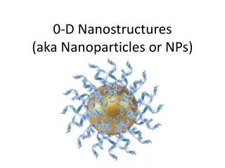
0D Nanostructures: Nanoparticles. SHAPES OF NANOPARTICLES. Basic motifs of inorganic nanocrystals: 0D spheres, cubes, and polyhedrons ; 1D rods and wires ; 2D discs, prisms, and plates . Top down approaches. Milling/Attrition Nanoparticles have a relatively broad size distribution

E N D
SHAPES OF NANOPARTICLES Basic motifs of inorganic nanocrystals: 0D spheres, cubes, and polyhedrons; 1D rods and wires; 2D discs, prisms, and plates.
Top down approaches Milling/Attrition Nanoparticles have a relatively broad size distribution have varied particle shape or geometry may contain a significant amount of impurities from the milling medium may contain defects resulting from milling used in the fabrication of nanocomposites and nanograined bulk materials In nanocomposites and nanograined bulk materials, defects may be annealed during sintering Repeated quenching Repeated thermal cycling may also break a bulk material into small pieces, if the material has very small thermal conductivity but a large volime change as a function of temperature. Fine particles can be produced The process is difficult to design and control so as to produce desired particle size and shape The process is limited to materials with very poor thermal conductivity but a large volume change
Bottom-up approach Nanoparticles synthesised by homogeneous nucleation from liquid or vapour Nanoparticles synthesised by heterogeneous nucleation on substrates Nanoparticles or quantum dots prepared by phase segregation through annealing appropriately designed solid material at elevated temperatures Nanoparticles synthesized by confining chemical reactions, nucleation and growth processes in a small space such as micelles
Categories of synthesis methods Thermodynamic equilibrium approach Kinetic approach
Thermodynamic approach Synthesis process consists of i. generation of supersaturation ii. Nucleation, & iii. Subsequent growth
Kinetic approach Formation of nanoparticles is achieved by either Limiting the amount of precursors available for growth e.g. molecular beam epitaxy) Confining the process in a limited space (e.g. aerosol synthesis or micelle synthesis)
Controlling Shape in the Nanoscale • Time • Minutes vs. hours • Temperature • Structure Difference Zinc Blend vs. Wurtzite • Surface Energetics • Different phases have different chemical potential and chemistry • Capping Organic Molecules • Different Molecules can attach to different phases • Monomer Concentration • Different Shape depending on concentrations
Desired Characteristics of nanoparticles Identical size of all particles (monosized particles/ paricles with uniform size distribution) Identical shape or morphology Identical chemical composition and crystal structure that are desired among different particles and within individual particles, such as core and surface composition must be the same Monodispersed (individually dispersed) particles (i.e. no agglomeration). If agglomeration does occur, nanoparticles should be readily redispersible
Nanoparticles Dimension: not > several hundred nm’s Can be Single crystal (aka nanocrystal) Polycrystalline amorphous Different morphologies e.g. spheres, cubes, platelets Quantum dots The characteristic dimension of the nanoparticles is sufficiently small and quantum effects are observed
Formation of nanoparticles dispersed in a solvent Most common approach Advantages Easiness of stabilization of nanoparticles from agglomeration extraction of nanoparticles from solvent surface modification and application processing control mass production
Synthesis of metallic nanoparticles (i.e. metallic colloidal dispersion) General method Reduction of metal complexes in dilute solutions The formation of monosized nanoparticles is achieved in most cases by a combination of low concentration of solute and polymeric monolayer adhered onto the adhered onto the growth surfaces Both low concentration and a polymeric monolayer would hinder the diffusion of growth species from the surrounding solution to the growth surfaces Various types of precursors, reduction reagents and polymeric stabilizers are commonly used
Colloidal gold Sodium citrate reduction of chlorauric acid Most commonly used method Add 1 ml of 0.5 % sodium citrate into a boiling dilute aqueous solution of chlorauric acid (~2.5 x 10⁻⁴ M) Keep the mixture at 100 oC until the colour changes, while maintaining the overall volume of the solution by adding water A large number of initial nuclei formed in the nucleation stage result in a large number of nanoparticles with smaller size and narrower size distribution The colloidal sol has excellent stability has uniform particle size of ~20 nm in diameter
Pt nanoparticles Radiolysis The gamma rays of Co-60 used to generate hydrated electrons, hydrogen atom and 1-hydroxylmethyl radicals Radicals reduce Pt2+ in K2PtCl4 to the zerovance state, which form Pt paticles (mean diameter 1.8 nm) Citrate reduction of PtCl62- Pt nanoparticles (diameter ~2.5 nm) obtained by boiling (1 h) a mixture of H2PtCl6 with sodium citrate Hydrogen reduction of K2PtCl4 Hydrolyse precursor (K2PtCl4 in dilute aq solution) to form hydroxides prior to hydrogen reduction. NaOH used as a catalyst to promote hydrolysis PVA used as a stabilizer
Ag nanoparticles UV illumination of aqueous solutions containing AgClO4, acetone and various polymer stabilizers UV illumination generates ketyl radicals via excitation of acetone and subsequent hydrogen abstraction from 2-propanol: The ketyl radical may undergo protolytic dissociation reaction: Both the ketyl radical and radical anions react with and reduce silver ions to silver atoms: Both reactions have a low reaction rate and thus favor the production of monosized Ag nanoparticles Using polyethyleneimine as polymer stabilizer: Size 7 nm, narrow size distribution
Ag nanoparticles Sonochemical reduction of an aq silver nitrate solution at 10oC in an atmosphere of Ar and H2. Water decomposed into hydrogen and hydroxyl radicals by ultrasound Hydrogen radicals reduce silver ions into silver atoms, which subsequently nucleate and grow to silver nanoclusters H2 removes hydrogen peroxides (which may oxidise silver nanoclusters to silver oxide) formed from hydroxyl radicals
Influence of reduction reagents A strong reduction reagent promotes a fast reaction rate, and favors the formation of smaller nanoparticles A weak reduction reagent induces a slow reaction rate and favors relatively larger particles
Influence of polymer stabilizers Polymer stabilizers are introduced primarily to form a monolayer on the surface of nanoparticles so as to prevent agglomeration of particles. A strong adsorption of polymer stabilizers would occupy the growth site and thus reduce the growth rate of nanoparticles. A full coverage of polymer stabilizer would hinder the diffusion of growth species from the surrounding solution to the growth site. Polymer stabilizers may interact with solute, catalyst, or solvent, and thus directly contribute to the reaction.
Nanotubes What’s a Nanotube? Carbon nanotubes are a new form of carbon material. They are produced through self-assembly when under optimal conditions and in the presence of the appropriate catalyst, one observes the growth of a hollow tubular structure whose surface represents a continuous honeycomb lattice of bonded carbon atoms. Their name derives from their size. Nanotubes are only a few nanometres wide (one ten-thousandth the width of a human hair), and their length can be thousands of times greater than their width.
Properties of Carbon Nanotubes Thermal : Thermally stable; can withstand temperatures of up to 2,000 degrees Celsius; the best heat conductors Electrical : Can be used as conductors or semi-conductors; can maintain large electrical currents; they conduct electricity much better than metals – best electron emitter Physical : Thin; hollow; lightweight; structural perfection on the atomic scale; enormous tensile strength; can be combined to form the strongest material in the world Optical : Strongly absorbs blue and ultraviolet light; photo luminescent and electro luminescent
Properties of CNTs SWNT’s have high tensile strength (~100 times that of steel, whereas their density is only about 1/6th that of steel. CNTs are used to enhance the mechanical strength of composite polymer materials. Armchair CNTs exhibit remarkably high electrical conductivity. Electrons can flow through the m–length nanowire with zero scattering and zero heat dissipation. CNTs have extremely high thermal conductivity (comparable to diamond and graphite). Potential application as interconnects for integral circuits.
Some Applications for Carbon Nanotubes Structural reinforcements in composites Field-emission flat-panel displays Conductive plastics High-performance fibers Chemical sensors Artificial muscles Portable X-ray machines Transistors Fuel cells Probe tips
Carbon allotropes Graphite The most abundant form of pure carbon on earth is which is composed of sheets of trigonally bonded carbon atoms arranged in hexagonal sheets (called graphene layers) Graphite is a soft, grey solid with high electrical conductivity along the direction of its graphene layers. Diamond formed under conditions of extreme temperature and/or extreme pressure is composed of tetrahedrally bonded carbon atoms is a precious stone which is transparent, insulating and the hardest material known on earth.
Carbon allotropes Fullerenes closed-caged carbon structures Buckminster fullerene, C60 molecule, is the most famous (discovered by Kroto in 1985). Carbon nanotubes highly crystallized carbon filaments a few nanometers in diameter and few microns long Discovered (1991, Iijima) whilst studying the carbonaceous deposit from an arc discharge between graphite electrodes They contain carbon atoms arranged in graphene sheets which were rolled together to form a seamless cylindrical tube can be single walled (i.e. one tube) or multiwalled (i.e. multiple concentric tubes).
Multi-walled Multiwalled nanotubes (MWNT) consist of multiple layers of graphite rolled in on themselves to form a tube shape. There are two models which can be used to describe the structures of multiwalled nanotubes
CNT structure & Electrical Properties Depending on the angle at which the graphite sheet is rolled up (called the roll-up vector), electrical transport in CNTs changes dramatically. Semiconductor properties Tubes with a helical twist in their structure Chiral nanotubes Metallic Achiral tubes are Zig-zag Armchair
Semiconducting nanotubes (2 out of every 3 random tubes) have a band gap between their conduction and valence bands In metallic tubes two mini-bands occupy the mid-gap state and quantum mechanical tunneling effectively leads to electrical conductivity. Helical CNTs have enabled the fabrication of the 1st transistor based on a single CNT (length 100 nm) Semiconducting and metallic CNTs can be separated using electrophoresis. Because of their different dielectric constants, the two types of nanotubes migrate towards opposite electrodes when in an alternating field. (Yields of segregated nanotubes : picograms!!!!) Precipitation of CNTs by evaporation of an octadecylamine solution can separate metallic from semiconducting nanotubes, based on different propensities for charge transfer with the electron donating solvent.
Carbon nanotubes Nanotubes are formed by rolling up a graphene sheet into a cylinder and capping each end with half of a fullerene molecule. Shown here is a (5, 5) armchair nanotube (top) a (9, 0) zigzag nanotube (middle) (10, 5) chiral nanotube. The diameter of the nanotubes depends on the values of n and m.
Types of nanotubes 3 types of nanotubes are possible depending on how the two-dimensional graphene sheet is "rolled up". armchair zigzag chiral nanotubes The different types are most easily explained in terms of the unit cell of a carbon nanotube - the smallest group of atoms that defines its structure (see top figure a). The so-called chiral vector of the nanotube, Ch, is defined by Ch = nâ1 + mâ2, where â1 and â2 are unit vectors in the two-dimensional hexagonal lattice, and n and m are integers. Another important parameter is the chiral angle, which is the angle between Ch and â1. Models of nanotubesWhen the graphene sheet is rolled up to form the cylindrical part of the nanotube, the ends of the chiral vector meet each other. The chiral vector thus forms the circumference of the nanotube's circular cross-section, and different values of n and m lead to different nanotube structures (see top figure a).
A carbon nanotube is based on a two-dimensional graphene sheet. (a) The chiral vector is defined on the hexagonal lattice as Ch = nâ1 + mâ2, where â1 and â2 are unit vectors, and n and m are integers. The chiral angle, q, is measured relative to the direction defined by â1. This diagram has been constructed for (n, m) = (4, 2), and the unit cell of this nanotube is bounded by OAB'B. To form the nanotube, imagine that this cell is rolled up so that O meets A and B meets B', and the two ends are capped with half of a fullerene molecule. Different types of carbon nanotubes have different values of n and m. (b) Zigzag nanotubes correspond to (n, 0) or (0, m) and have a chiral angle of 0°, armchair nanotubes have (n, n) and a chiral angle of 30°, while chiral nanotubes have general (n, m) values and a chiral angle of between 0° and 30°. According the theory, nanotubes can either be metallic (green circles) or semiconducting (blue circles).
Single-walled nanotubes The (n,m) nanotube naming scheme can be thought of as a vector (Ch) in an infinite graphene sheet that describes how to "roll up" the graphene sheet to make the nanotube. T denotes the tube axis, and a1 and a2 are the unit vectors of graphene in real space. SWNTs: diameter close to 1 nm, tube length many thousands of times larger than the diameter The structure of a SWNT can be conceptualized by wrapping a one-atom-thick layer of graphene into a seamless cylinder. The way the graphene sheet is wrapped is represented by a pair of indices (n,m) called the chiral vector. The integers n and m denote the number of unit vectors along two directions in the honeycomb crystal of graphene. Armchair nanotubes are formed when n = m and the chiral angle is 30°. Zigzag nanotubes are formed when either n or m are zero and the chiral angle is 0°. All other nanotubes, with chiral angles intermediate between 0° and 30°, are known as chiral nanotubes.
SWNTs are a very important variety of carbon nanotube because they exhibit important electric properties that are not shared by the multi-walled carbon nanotube (MWNT) variants. SWNTs are the most likely candidate for miniaturizing electronics past the microelectromechanical scale that is currently the basis of modern electronics.
Applications of CNTs Chemical sensors Fuel cells Field effect transistors Electrical interconnects Mechanical reinforcers
Formation of a gold-silica core-shell structure Step 1. Formation of gold nanoparticles (colloidal gold) Step 2. Modifying the surface of gold nanoparticles by introducing a monolayer of organic molecules through self-assembly Step 3. Deposition of silica shell
Step 1. Formation of gold nanoparticles (colloidal gold) Step 2. Modifying the surface of gold nanoparticles by introducing a monolayer of of organic molecules through self-assembly A freshly prepared aqueous solution of APTS (2.5 mL, 1 mM) is added is added to 500 mL of gold colloidal solution under vigorous stirring for 15 min. A complete coverage of one monolayer of APTS is formed on the gold particle surface. During this process the previously adsorbed, negatively charged citrate groups are displaced by APTS molecules, with the silanol groups pointing into solution. The process is driven by the large complexation constant for gold amines. The silane groups in APTS molecules in aqueous solution undergo rapid hydrolysis and convert to silanol groups, which may react with one another through condensation reactions to form 3D network. However the rate of condensation is rather slow at low concentration. During the self-assembly of APTS on the surface of gold particles, the pH needs to be maintained above the isoelectric point of silica, which is 2 – 3, so that the silanol groups is negatively charged. In addition, the pH is required to ensure the the adequate negative surface charge on the gold nanoparticles, so that the positively charged amino groups are attracted to the gold surface. Step 3. Deposition of silica shell A silica sol prepared by slowly reducing the pH of a 0.54 wt % sodium silicate solution to 10 – 11 is added to the gold colloidal solution (with a resulting pH of ~8.5) under vigorous stirring for at least 24 hours. A laer of silica of 2 – 4 nm thick is formed on the modified surfaceof the gold nanoparticles. In this step slow condensation or polymerisation reaction is promoted by controlling the pH, so that the formation of a thin, dense and relatively homogeneous silica layer can be produced.
Step 2. Modifying the surface of gold nanoparticles by introducing a monolayer of organic molecules through self-assembly A freshly prepared aqueous solution of APTS (2.5 mL, 1 mM) is added is added to 500 mL of gold colloidal solution under vigorous stirring for 15 min. A complete coverage of one monolayer of APTS is formed on the gold particle surface. During this process the previously adsorbed, negatively charged citrate groups are displaced by APTS molecules, with the silanol groups pointing into solution. The process is driven by the large complexation constant for gold amines. The silane groups in APTS molecules in aqueous solution undergo rapid hydrolysis and convert to silanol groups, which may react with one another through condensation reactions to form 3D network. However the rate of condensation is rather slow at low concentration. During the self-assembly of APTS on the surface of gold particles, the pH needs to be maintained above the isoelectric point of silica, which is 2 – 3, so that the silanol groups is negatively charged. In addition, the pH is required to ensure the adequate negative surface charge on the gold nanoparticles, so that the positively charged amino groups are attracted to the gold surface.
Step 3. Deposition of silica shell A silica sol prepared by slowly reducing the pH of a 0.54 wt % sodium silicate solution to 10 – 11 is added to the gold colloidal solution (with a resulting pH of ~8.5) under vigorous stirring for at least 24 hours. A layer of silica of 2 – 4 nm thick is formed on the modified surface of the gold nanoparticles. In this step slow condensation or polymerisation reaction is promoted by controlling the pH, so that the formation of a thin, dense and relatively homogeneous silica layer can be produced.
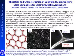
Preparation of nanoparticles • Plasma processing - Both thermal (plasma arc, plasma torch, plasma spray) and low temperature (cold) plasma (discussed in Section 4) are used • Chemical Vapor Deposition - Either on a substrate or in the gas phase (for bulk production) - Metallic oxides and carbides • Electrodeposition • Sol-gel processing • Ball mill or grinding (old fashioned top-down approach) Key Issue: Agglomoration
QUANTUM DOTS Also referred to as spherical nanoparticles, nanocrystals etc. Properties based on the optical features of their absorption and emission spectra. Semiconductor nanostructure Motion of conduction band electrons confined Also refers to holes and excitons Hole-electron separation known as Exciton Bohr radius. When size of particle same size as EBR then treat En levels as discrete. En levels separated and leads to quantum confinement An ‘artificial’ atom 2-10 nm (10-50 atoms) up to 100-100000 nm Compare with quantum wire and well (confined in two and one DIRECTION) Size controls band gap. High quantum yields
• Synthetic “droplets” containing anything from a single electron to thousands of atoms but behave like a single huge atom. • Size: nanometers to microns • These are nanocrystals with extraordinary optical properties - The light emitted can be tuned to desired wavelength by altering the particle size - QDs absorb light and quickly re-emit but in a different color - Colors from blue to IR • Common QDs: CdS, CdSe, PbS, PbSe, PbTd, CuCl… • Manufacturing - Wet chemistry - Template synthesis (zeolites, alumina template)
SYNTHESIS Can be synthesized by single-source precursor route or conventional route Conventional route: involves the reaction of metal salts and a base, NaOH or alkoxides in the presence of stabilizing organic molecules. Single-source precursor: involves the preparation of metal complexes which in turn undergo thermal decomposition in a coordinating organic solvent.
Conduction Band Energy levels Radiationless decay Fluorescence Band gap Absorption Valence Band Small Molecules Qdots Semiconductors Electronic structure of Qdots Source: Bala Manian, Quantum Dot Corp.
Optical properties of nanoparticles Ordinary light excites all color quantum dots. (Any light source “bluer” than the dot of interest works.) Quantum dots change color with size because additional energy is required to “confine” the semiconductor excitation to a smaller volume. Source: Bala Manian, Quantum Dot Corp.
Size and material dependent optical properties Material band-gap determines the emission range; particle size tunes the emission within the range Nanocrystal quantum yields are as high as 80% Narrow, symmetric emission spectra minimize overlap of adjacent colors Source: Bala Manian, Quantum Dot Corp.
Constants and calculated excitonic diameter for some II–VI and III–V materials
APPLICATIONS • LEDs, solar cells, solid state lighting • Biomedical - Bioindicators - Lateral flow assays - DNA/gene identification, gene chips - Cancer diagnostics • Biological Labeling Agent Organic Dye Quantum Dot • Broad output spectrum • Sharper spectrum • Fades quickly ~ 100 ps • 5-40 ns • Unstable • Stable output over time • One dye excited at a time • Multicolor imaging, multiple dyes excited simultaneously


![How many nm are in a metre? [1]](https://cdn1.slideserve.com/2509766/slide1-dt.jpg)