Download

1 / 27
280 likes | 599 Vues
The CERN LHC central timing A vertical slice. Pablo Alvarez Jean-Claude Bau Stephane Deghaye Ioan Kozsar Julian Lewis Javier Serrano. Talk layout. The CERN central timing overview Accelerator complex, LHC injector chain Cycles and Super-cycles The LHC beam, UTC machine, Synchronization

E N D
The CERN LHC central timingA vertical slice Pablo Alvarez Jean-Claude Bau Stephane Deghaye Ioan Kozsar Julian Lewis Javier Serrano
Talk layout • The CERN central timing overview • Accelerator complex, LHC injector chain • Cycles and Super-cycles • The LHC beam, UTC machine, Synchronization • Hardware • Central timing layout • Reflective memory • Event frames and their distribution • Clocks and calibration • The Controls Timing Receiver module CTR • The Multitasking Timing generator module MTT • Safe Parameters Verification • The CTR hardware support for safety critical situations • Postmortem behavior • Software • LSA and FESA requirements • Telegrams and events • MTT tasks and event tables • The table compiler, assembler and task loader
….…. ….…. CERN accelerator networksequenced by central timing generator LHC Experimental area SPS Experimental area CPS Experimental Area PSB
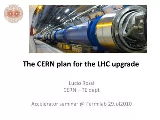
TI8 Dump SPS CPS TCLP PSB Linac TI2 Dump SPS Dump D3 Dump R2 LHC The LHC Proton Injector ChainStrongly time coupled R1 LHC CNGS
The LHC Beam start-ramp event The LHC timing is only coupled by extraction LHC Injection plateaux Injection Injection • LSA Beam request: • RF bucket • Ring • CPS batches Extraction Extraction Extraction Forewarning Extraction Forewarning SPS injection plateaux SPS Cycle for the LHC CPS Batch 1 CPS Batch 2 CPS Batch 3 CPS Batch 4 PSB1 PSB1 PSB2 PSB2 PSB3 PSB3 PSB4 PSB4
CBCM Sequence Manager LSA Sequencer “LSA” TI8/TI2 Dump The Central Timinglayout LHC User Master ON/OFF LHC Fill Requests: Bucket Ring Batches Request TI8/TI2 Dump CS-CCR-CTMGW FESA API LHC Fill Requests: Bucket Ring Batches Reflective Memory Link Request LHC User Normal Spare LIC Sequence LHC Central Timing CBCM Controlling Injector Chain SPS destination request R1,R2 LHC Timing Inhibits Requests Interlocks SIS TI8/TI2 & SPS Dump Inhibits LSA Master CPS Batch Request 1,2,3,4 SEX.FW1K SPS.COMLN.LSA_ALW CTR HIX.FW1K LSA changes Allowed LIC Timing
Reflective memory LHC Timing generator A LHC Timing generator B Identical except ID event 2Gbit/S Token ring VMIACC-5595 Single Mode Hub Reflective memory: A and B must always be in the same state. If no restrictions for switch over Protects token ring 64Mbyte VMIPMC-5565 Reflective memory LHC Gateway Implements FESA API
Library Driver Shared memory segment XMEM segment Shared memory segment XMEM segment Shared memory segment XMEM segment Shared memory segment XMEM segment Reflective Memory XMEM • Daemon • DMA manager • Topology management • Memory initialization Configuration data Synchronization Library calls Client RT task Token Ring DMA
A T CODE PAYLOAD Event frames • Timing frames are encoded at 500KBit/S using a 1MHz clock. • Each frame carries 32 data bits. • One frame transmitted each 128us, 8 per millisecond. • Frames are broken into bit fields • 4 Bits Accelerator [A] • 4 Bits frame Type [T] • 8 Bits Code [CODE] • 16 Bits Payload [PAYLOAD] • Some frame are recognized by the hardware and cause special treatment • Two UTC frames carry the time of day in their payload • Millisecond frames are always sent in phase with the PPS • Telegram frames are stored in double buffers • Event frames cause counters to be loaded and triggered and may produce bus interrupts Millisecond Millisecond
PPS 10 MHz CTRP 1 KHz Delay 40MHz Clock Source &Calibration Symmetricom CS4000 portable Atomic Clock GPS Basic Period 1200/900/600 ms Event tables Synchronization module in each timing generator crate GPS One pulse per Second Advanced (100us) One pulse per Second PLL One pulse per Second MTT Multitask Timing Generator MTT Synchronized 1KHz (slow timing clock) Symmetricom XLI Phase locked 10MHz RS485 Timing RS485 Timing 40MHz PLL Phase locked 10MHz CERN UTC Time CERN UTC Time Timing receiver Control System Phase looked 40 MHz Event encoding clock UTC time (NTP or GPS) Set once on startup & on Leap Seconds 25ns steps External events
Controls Timing Receiver CTR Timing 22Bit 50MHz Counters Content Addressed Memory - Triggering • Start • Previous • External • Event • Clock • Previous • 40MHz harmonic • External • Modes • Once • Multi-pulse • Burst • Trigger • Event frame • Wildcard • Telegram • Action • Output • Bus interrupt • Output • TTL/TTL bar • Pulse width Bus Interrupt Hybrid PLL 40MHz Delay Lookup Load Trigger Output Frame Decoder Counter Configurations Loader UTC TGM TGM CTRV – CTRI – CTRP formats
Cycle A Loading Event C0 C1200 Counting Telegram Ready Counter Start Counter Output Telegram Ready Acquisition Performed by RT task • Counter Load • Delay Cycle A • Clock Cycle A • Enable Cycle A Telegram Timing receiver function • Counting Sequence
Multitask Timing Generator MTT • Implements general purpose CPU with memory mapped IO registers • Event Out register • VME P2 In register • Free running millisecond register • Op-codes are triadic: AND REG,REG,REG – AND 0x7,VMEP2,TMP • Arithmetic and logical • Move indexed, literal, register • Wait value, relative • Conditional branch • Interrupt host • Hardware multitasking for 16 tasks based on work space pointer, all available to host • 32 local registers per task • 218 Global registers • 6 Memory mapped IO registers • Host processor access to all registers • Tasks defined from host via Task Control Block • PC • PC Offset • Processor Status Word • Command and status registers allow host access to running tasks
MTT hardware module See: The LHC central timing hardware implementation P. Alvarez, J. Lewis, J. Serrano CERN, Geneva, Switzerland This conference
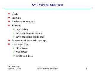
BLM Kickers Kickers BIS BIS BIS BLM BLM Timing Network Simplified Layout of the Safe Machine Parameters Distribution If length > 5m SMP @ 10Hz 16Bit 1010 (Flags, E & Int.) Events, UTC, & Telegrams (including SMP) Flags TTL Hw Output Energy A EXP Line driver BEM CTRx @1kHz-24Bit 108 CTRx CTRx CTRx LHC Timing Generator Safe Machine Parameters Controller for LHC BEM EXP Energy B CTRV CTRV BCT “A” CTRV I_beam1 & 2 (CTRV) BCT “B” BIS CTRV CTRV Reads thresholds Reads status LHC Beam Sequencer Management Critical Settings CTRV CTRV CTRV • main Safe Machine Parameters for LHC: • Energy • Safe Beam Flags • Movable Devices Allowed Flag • Safe Injection Flags (new) B.P. 23rd Aug.07
CTRV Timing receivers Safe Parameters HX.SBF1 & Safe Load Out Beam Energy is available directly on P2 serially encoded Delay=1 ms Start Clock Safe Beam Flag (Level) GMT 1MHz Divide Pulse Stretcher Out Delay=40 Safe Start Clock Stop 40MHZ Dangerous HX.SBF1 & Safe Load Out Delay=10^6 ms Start SBF1/2 sent at 10 Hz Clock
Postmortem Event suppression Two counters are used in the CTR, one per Beam-Permit-Flag (BPF) Each counter clock is connected to one of the BPF flags The "Disable Post-Mortem Ring 1" event disables the counter connected to BPF-1 The "Enable Post-Mortem 1" event enables the counter connected to BPF-1 When the counter is disabled and the BPF goes down nothing happens When its enabled the counter makes an output triggering the PM event It will be sent twice if both counters are enabled and both rings are dumped CTR CTG-MTT BPF1 CLK Delay=1 Disabled Disabled Warn-Inject Loads LSA VME/P2 PM-1 Suppress Table BPF2 CLK Delay=1 Enabled Enabled LHC GMT Dump-1 PM Disable-1, Enable-1
LSA and FESA • The FESA API is implemented on the LHC timing gateway • Accesses timing generators across reflective memory • Implements • Load or Unload event table • Get running tables list • Set event table run count and synchronization event • Stop or Abort event table • Set telegram parameters • Send event • Read status of tasks and MTT module
Telegrams and events • The telegram is a set of parameters that describes the machine state • Telegrams are distributed each second • Each telegram parameter is shadowed by an event • Real time tasks subscribe to events and read the telegram to know the current machine state
Event tables • Event tables are ASCII strings sent from LSA to the LHC timing gateway • Each entry in the table contains • The name of the event to send “HX.START-RAMP” • The relative time to wait in seconds before sending the event “1.01” • The payload the event will carry “0x0005” • A carriage-return <CRTN> terminates the entry • The table run count and synchronization event will be filled in later when the table is to be executed
Event Table Processing Event Table LSA HX.Start-Ramp 1.01 0x5 HX.Start-Freq 0 0x05 FESA API Event Table template Table Compiler waitr MSFR,1001 movv 0x14020005 EVOUT movv 0x14030005 EVOUT Translation Translate and Merge MTT Program Memory Table Task Garbage Collect Load object Initialize TCB Run task Assemble task Assembler Task Loader Data Reflective Memory Object Code Process Hot Standby
Event Table processing • The table-compiler output assembler code containing wait and send operations corresponding to the table entries • WAITR MSFR 1001 • MOVE 0x14020005 EVOUT • The table-compile then builds a task by including the above output into an event table task template • The assembler takes the above code and assembles it into position independent object code • The table loader locates free program memory (it may need to do garbage collection) and loads the object into it. It then initializes a TCB and starts the task running. • The task runs and sets its status to “Waiting-run-parameters” and waits for LSA to set them • Positive Run-Count (Or run forever) • Synchronization event (Or ignore)