Download
1 / 51
520 likes | 694 Vues
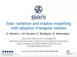
Adaptive Solar Radiation Numerical Model. F. Díaz, G. Montero, J.M. Escobar, E. Rodríguez, R. Montenegro*. FEMTEC 2011, 9–13 May 2011, South Lake Tahoe, NV, USA. MEC y FEDER Projects : CGL2008-06003-C03 and UNLP08-3E-010. http://www.dca.iusiani.ulpgc.es/proyecto2008-2011. Contents.

E N D
Adaptive Solar Radiation Numerical Model F. Díaz, G. Montero, J.M. Escobar, E. Rodríguez, R. Montenegro* FEMTEC 2011, 9–13 May 2011, South Lake Tahoe, NV, USA MEC y FEDER Projects: CGL2008-06003-C03 and UNLP08-3E-010 http://www.dca.iusiani.ulpgc.es/proyecto2008-2011
Contents • 1. Introduction • 2. Terrain surface triangulation and detection of shadows • 3. Solar radiation modeling • -Solar radiation equations for clear sky • Beam radiation • Diffuse radiation • Reflected radiation • -Solar radiation for real sky • -Typical meteorological year (TMY) • 4. Results • 5. Conclusions and future research
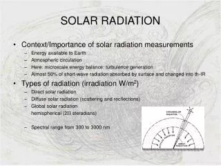
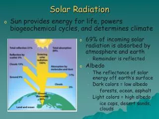
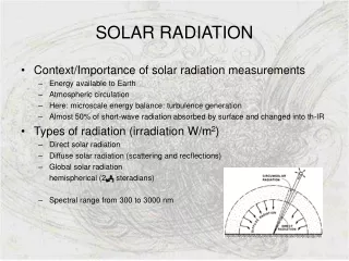
Introduction • Solar power is one of the most appreciate renewable energies • Three groups of factors determine the interaction of solar radiation with the earth’s atmosphere and surface • a. Earth’s geometry, revolution and rotation (declination, latitude, solar hour angle) • b. Terrain (elevation, albedo, surface inclination/orientation, shadows) • c. Atmospheric attenuation (scattering, absorption) by • c.1. Gases (air molecules, ozone, CO2 and O2) • c.2. Solid and liquid particles (aerosols, including non-condensed water) • c.3. Clouds (condensed water) • Correctestimationneedsanaccuratedefinition of theterrainsurface and theproducedshadows. Previousworks (CNME 1994, SE 2009, ECT 2010, …) • A typical meteorological year (TMY) for each available measurement station has been developed.
Introduction Topography Shadows Albedo • Beam Radiation • Diffuse Radiation • Reflected Radiation • Global Radiation Clear Sky ExperimentalData Real sky
Terrain surface mesh and shadows • Build a sequence of nested meshes from a uniform triangulation of a • rectangular region, such that the mesh level l is obtained by a global • refinement of the previous level l−1 with the 4-T Rivara’s algorithm • Define a new sequence until level m’ ≤ m applying a derefinement algorithm Two derefinement parameters εh and εa are introduced and they determine the accuracy of the approximation to terrain surface and albedo, respectively. (uniform initial mesh)
Terrain surface mesh and shadows • Build a sequence of nested meshes from a uniform triangulation of a • rectangular region, such that the mesh level l is obtained by a global • refinement of the previous level l−1 with the 4-T Rivara’s algorithm • Define a new sequence until level m’ ≤ m applying a derefinement algorithm Two derefinement parameters εh and εa are introduced and they determine the accuracy of the approximation to terrain surface and albedo, respectively.
Terrain surface mesh and shadows • Build a sequence of nested meshes from a uniform triangulation of a • rectangular region, such that the mesh level l is obtained by a global • refinement of the previous level l−1 with the 4-T Rivara’s algorithm • The number of levels m of the sequence is determined by the resolution • of the terrain elevation map • Define a new sequence applying a derefinement algorithm. The number of levels of the derefined sequence is m’ ≤ m • Define a new sequence until level m’ ≤ m applying a derefinement algorithm • Two derefinement parameters, εh and εa , are introduced and they determine the accuracy of the approximation to terrain surface and albedo, respectively. Two derefinement parameters εh and εa are introduced and they determine the accuracy of the approximation to terrain surface and albedo, respectively.
Terrain surface mesh and shadows Day angle Hour angle Sun declination Solar altitude and Solar azimuth Solar beam direction
Terrain surface mesh and shadows The incidence solar angle δexp is then computed for each triangle, i.e. the angle between the solar beam and the normal triangle directions
Terrain surface mesh and shadows Construct a reference system x’, y’ and z’, with z’ in the direction of the beam radiation, and the mesh is projected on the plane x’y’
Terrain surface mesh and shadows Check for each triangle Δ of the mesh, if there exists another Δ’ that intersects Δ and is in front of it, i.e., the z’ coordinates of the intersection points of Δ’ are greater than those of Δ.
Terrain surface mesh and shadows The analysis of the intersection between triangles involves a high cost Therefore, we have considered 4 or 16 warning points (nw) Lighting factor of each triangle Lf = 1 - i/nw where i = 0, …, nw, is the number of shaded warning points of Δ.
Terrain surface mesh and shadows 12:00 hours 14:00 hours 14:00 hours 12:00 hours 16:00 hours 18:00 hours 16:00 hours 18:00 hurs
Solar radiation modelling General aspects: We have introduced the use of adaptive meshes for surface discretizationand a new method for detecting the shadows over each triangle of the surface. This solar radiation model is based on the work of Šúri and Hofierka Calculations flow: We first calculate the solar radiation under the assumption of clear sky for all the triangles of the mesh. Typical Meteorological Year (TMY) is evaluated for all the involved measurement stations. Solar radiation values are corrected for a real sky by using the TMY from the available data of the measurement stations in each time step along an episode. Steps 1 and 3 are repeated for each time step and finally, the total solar radiation is obtained integrating all the instantaneous values in each triangle.
Solar radiation modelling Solar radiation equations for clear sky Solar radiation types Beam Diffuse Reflected
Solar radiation modelling Solar radiation equations for clear sky Solar constant Beam radiation Extraterrestrial irradiance G0normal to the solar beam Correction factor Linke atmospheric turbidity factor Beam irradiance normal to the solar beam Gb0c = G0 exp{−0.8662TLKmδR(m)} Relative optical air mass Beam irradiance on a horizontal surface h0: the solar altitude angle Lf: the lighting factor Gbc(0) = Gb0c Lfsin h0 Beam irradiance on an inclined surface δexp: the incidence solar angle Gbc(b) = Gb0cLfsinδexp
Solar radiation modelling Solar radiation equations for clear sky Diffuse radiation Diffuse transmission Diffuse radiation on horizontal surfaces Diffuse radiation on inclined surfaces Function depending on the solar altitude Sunlit surfaces ho ≥ 0.1 ho < 0.1 Shadowed surfaces
Solar radiation modelling Solar radiation equations for clear sky Reflected radiation Mean ground albedo
Solar radiation modelling Solar radiation under real-sky Values of global radiation on a horizontal surface for real sky conditions G(0) are calculated as a correction of those of clear sky Gc(0) with the clear sky index kc If some measures of global radiation Gs(0) are available at different measurement stations, s , the value of the clear sky index at those points may be computed as s Then kc may be interpolated in the whole studied domain, for example:
Solar radiation modelling Typical Meteorological Year (TMY) To obtain accurate real sky values of global irradiation, the evaluation of a TMY is used to avoid results based on a particular year weather conditions For each station, we compute the daily typical meteorological year of irradiation values using weight means to smooth the irregular data. For example, we can use the following statistic metrics: Means Medians
Solar radiation modelling Typical meteorological year (TMY) Td: Maximum md: Mean Md: Median Day of the year
Solar Model Summary SOLAR MODEL Clear Sky Irradiance (W/m2) Real Sky Irradiance (W/m2) Kc Measurement Stations Irradiation (J/m2) Numerical Integration in a period of time Clear Sky Index at Stations Clear Sky Irradiation (J/m2) Interpolation Real Sky Irradiation (J/m2) Clear Sky Index at any Location Kc
Results The studied case corresponds to Gran Canaria, one of the Canary Islands in the Atlantic Ocean at 28.06 latitude and −15.25 longitude. TMY (1998 – 2008) for all the stations in Gran Canaria Island were obtained for every month. • The average global radiation (real sky), varies from: • 10.6 MJ/m2 per day in December • 25.6 MJ/m2 per day in June
Results Gran Canaria Island
Results Geolocation of different stations on Gran Canaria Island Elevation map of Gran Canaria
Results Macaronesic laurisilva 0.05 Salt mine 0.6 Albedo map of Gran Canaria
Results Gran Canaria 2-D Discretization
Results Gran Canaria 3-D Discretization
Results 5866 nodes 11683 triangles Triangular mesh adapted to topography and albedo
Results EXAMPLE 82 − 87% of the mean global irradiation Clear sky beam radiation map (J/m2) December 2006
Results EXAMPLE 13 − 18% of the mean global irradiation Clear sky diffuse radiation map (J/m2) December 2006
Results EXAMPLE 0 − 0.5% of the mean global irradiation Clear sky reflected radiation map (J/m2) December 2006
Results Clear sky global radiation map (J/m2) December 2006 Real sky global radiation map (J/m2) December 2006
Results Annual evolution of the computed monthly average per day (TMY) for both, clear sky and real sky global radiation DE DE
Results Percentage decrement: Real sky to clear sky TRADE WINDS Months
Results Influence of the trade winds: Annual Wind Rose for Canary Islands Frequency (%)
Results Influence of the trade winds:
Results SIMULATIONS: Monthly average Real Sky radiation (J/m2) January April
Results SIMULATIONS: Monthly average Real Sky radiation (J/m2) July October
Results SIMULATIONS: Monthly average Real Sky radiation (J/m2) October N
Results SIMULATIONS: Monthly average Real Sky radiation (J/m2) April N
Results Real and Clear Sky Irradiance Daily irradiance (W/m2) for Maspalomas Station January 15th July 15th Horizontal surface
Results Real and Clear Sky Irradiance Daily irradiance (W/m2) for Maspalomas Station. July, 15th South oriented. Panel inclination: 0º South oriented. Panel inclination: 10º Maximum irradiance.13 UTC.
Results Real and Clear Sky Irradiance Daily irradiance (W/m2) for Las Palmas de G.C. January 15th Panel inclination: 60º Orientation: East Orientation: West
Results Solar Power Generation and Electrical Network Management: Photovoltaic and Solar Thermal Real Sky Irradiance (W/m2) Solar PV Model Solar Thermal Model Electric Power Generation
Conclusions • The adaptive triangulation related to the topography and albedo is essential in order to obtain accurate results of shadow distribution and solar radiation • Adaptive meshes lead to a minimum computational cost, since the number of triangles to be used is optimum • Statistical treatment of data is useful to reach approximated values of the radiation distribution • Typical meteorological year (TMY) is the departure point to estimate the real sky radiation values • The model allows to choose the most suitable zone in the island for solar power stations • Rectangular collectors can be included in the model as composed by two triangles on the same plane
Future research • Improve the interpolation procedure of clear sky index • Calculate the optimal orientation and inclination of solar collectors for each location • Optimal selection of the warning points for detecting the shadows • Determinate the shadow boundary using ref/deref and mesh adaption by moving nodes • Fully parallelization of the simulation • Develop a predictive solar code based on meteorological models (MM5, WRF, HIRLAM)