SOLAR RADIATION
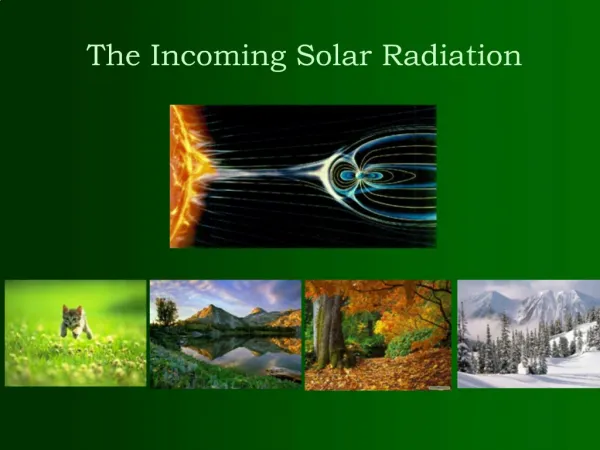
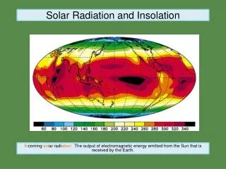
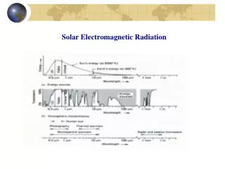
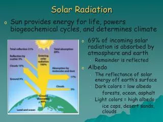
SOLAR RADIATION. Context/Importance of solar radiation measurements Energy available to Earth Atmospheric circulation Here: microscale energy balance: turbulence generation Almost 50% of short-wave radiation absorbed by surface and changed into th-IR Types of radiation (irradiation W/m 2 )

SOLAR RADIATION
E N D
Presentation Transcript
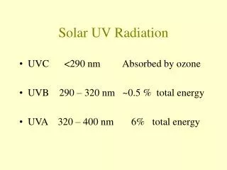
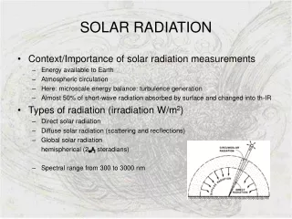
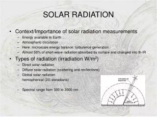
SOLAR RADIATION • Context/Importance of solar radiation measurements • Energy available to Earth • Atmospheric circulation • Here: microscale energy balance: turbulence generation • Almost 50% of short-wave radiation absorbed by surface and changed into th-IR • Types of radiation (irradiation W/m2) • Direct solar radiation • Diffuse solar radiation (scattering and recflections) • Global solar radiation hemispherical (2 steradians) • Spectral range from 300 to 3000 nm
SENSOR TYPES: AN OVERVIEW OF TECHNOLOGIES • Direct solar radiation: Pyrheliometers • Tracking of solar position (azimuth and zenith angles) • Net radiation level: Radiometers • Sum of direct and diffuse solar radiation minus reflected • PPFD: Quantum sensors • Photosynthetic light spectrum or PPFD • Total (global) radiation: Pyranometers • Thermopile arrays • Electrical output prop. to absorbed radiation • Thermocouples in series or in parallel • Photovoltaic detectors • Si – photodiodes (barrier-layer cell) • Potential at junction between two materials • Rapid response time
OUR CHOICE:THE DAVIS SOLAR RADIATION SENSOR 6450 • General information • Si photodiode with wide spectral response (sealed) • Convection cooling of body, run-off path for water • Cutoff ring for cosine response, level indicater, alignment fins • In-build amplifier • Manufacturer’s specifications • Power requirements: 3 VDC (10%); 1 mA; 3 mW • Analog output [0,+3VDC]; 1.67 mV per W/m2 • Operating environmental conditions: • Temperature: -40° to +65°C • Temperature corrections: coeff = 0.12% per °C; ref temp = 25°C • Sensor specifications • Spectral response: 400 (300) to 1100 nm • Output Range: 0 to 1800 W/m2 • Cosine Response 3% (0°-70° i. angle); 10% (70°-80°i.a.) • Accuracy: 5% of full scale (ref: Eppley PSP at 1000 W/m2) • Drift: up to 2% per year
OUR CHOICE:THE DAVIS SOLAR RADIATION SENSOR 6450 • Sensor components and dimensions • Diffuser with ‘excellent’ cosine response • Cable (industrial version: 5 m) • Dimensions: 51 mm x 70 mm x 57 mm • Weight: 226 g • Mounting • Top of stand • Needs flat surface with holes for fixing • 3 screws and springs for levelling • Fins for optical alignment
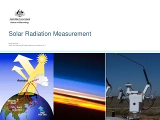
CALIBRATION REQUIREMENTSIMPROVED ACCURACY LOW-COST SENSORS • Studies by King et al. at Sandia National Laboratories • Achieve better accuracy (3%) using photodiodes instead of expensive thermopile devices (2%) • Main factors influencing accuracy • Solar spectral influence • Solar angle-of-incidence • Sensor’s response to direct irradiance influenced by cosine of solar AOI & optical characteristics of front surface • Significant measurement errors at high AOI • Operating temperature • Calibration methodology • Determine AMa and AOI functions (empirical curves) • Determine calibration constant Cn (in mV) for standardized AMa solar spectra, at a reference temperature To • Apply corrections for an improved estimate of the total (broadband) irradiance Et:
CALIBRATION REQUIREMENTSIMPROVED ACCURACY LOW-COST SENSORS • Solar spectral influence • Changes of solar spectral distribution over the day • Compute spectral mismatch parameter M (ASTM) • Option to relate M to the absolute optical airmass AMa and obtain a continuous spectral mismatch parameter • Solar angle-of-incidence • Influence depends on pyranometer’s optical characteristics (diffuser) • AOI function • Operating temperature • Other factors: • Mechanical and optical asymmetries, linearity of response, path across pyranometer, response time, stability
CALIBRATION REQUIREMENTSCLASSIFICATION & INDICATIONS • WMO classification of Davis 6450 pyranometer • Second class pyranometer • WMO calibration methods (using sun or lab source) • Comparison with standard pyrheliometer • Comparison with standard pyranometer (natural conditions) • Comparison on laboratory optical bench • Comparison in laboratory integrating chambers • Calibrate in the normal position of use • Comparison with reference pyranometer • Simultaneous operation of both instruments • Long period for representative results in typical conditions • Calibration factor: k = R kr (R-response ratio test/reference) • Take temperature into account • Davis sensors individually calibrated against secondary standard – standard calibrated against Eppley Precision Spectral Pyranometer in natural daylight
SITE SELECTION CONSIDERATIONS • Site selection • Site should be free from any obstruction above plane of sensing element • Shadow possibilities at any time of year have to be taken into account • Should be away from light-coloured walls or reflective objects • Should not be exposed to artificial radiation sources • Keep at certain distance from buildings or obstructions • Here: these considerations will probably not be taken into account • Avoid vibrations due to high winds, use rigid platform • Installation • Careful optical levelling of instrument, check plotting irradiance throughout a day • Maximum cable length and weatherproofed junctions • Operation • Sampling rate • Integration of data
MAINTAINANCE REQUIREMENTS • Inspection frequencies (ASTM standards) • Daily for cleaning • Semi-annual for inclination angle verification • Annual for recalibration and general deterioration inspection • Care and maintainance • Wipe dry and clean diffuser using cloth and ethyl alcohol • Gently remove solid deposits: frozen snow, frost or rime • Recalibration • Observed annual drift of 2%, for higher accuracy, calibrate once a year • Basic calibration procedures should be employed if preserved standards available • Quality control with long-term plots of solar noon irradiance value during clear sky conditions
Si Photodiode Visible to UV • What is a photodiode? -> A component semiconductor able to detect a radiation, which collects the visible signal and transforms it into electric signal. Family of the active photoreceivers, it requires to be polarized in reverse by an external food. -> 3 distinct areas are located: • charging space (ZCE) • Neutral region of type N • Neutral region of type P
Si Photodiode Visible to UV • Dimensional outlines -> Side View: Width: 5,5 mm Width window: 3,1 mm Height: 16,5 mm -> Top View: Distance connects: 2,55mm
Si Photodiode Visible to UV • General Characteristics : • - package= 18mm • - Active area size= 1,2 mm2 • - Reverse voltage(VRMax)= 30 Volts • - Operating temperature(Topr)= -40 to +100 • - Storage temp.(Tstg)= -55 to +125 celsius • -> Analogical dispositif with borosilicate glass
Si Photodiode Visible to UV • Electrical and optical Characteristics : • Spectral response range from 320 to 1100 nm • Peak (sensitivity wave length) lambda= 960 nm « spectral response » • PhotoSensitivity (S)= 0,6 (A/W) « photosensitivity »
Si Photodiode Visible to UV • Warning: Photodiodes (Ge) have a more significant photosensitivity but their dark current is notable ID = 10 uA. It is thus preferable to use photodiodes (Si) (ID near 10 pA) for the detection of weak illuminations. • Dark current ID= 2 pA • - Temp. coefficient of ID= 1,12 times / degree
Si Photodiode Visible to UV • Electrical and optical Characteristics : • - Rise time : 0,4 micro sec. «rise time/ load resistance» • - Terminal capacitance(Ct)= 140 pF • - Shunt resistance (Rsh)= 5 to100 GOhm « shunt resistance » • This device goes to necessite the use of an amplifier of impedance. About alternative technologies we have: laser, and every works with wavelength.
Si Photodiode Visible to UV • Precision and accuracy: • Near the microseconde • High reliability • High linearity(->relationship between the collected ray and the electrical current product is strictly linear) • Maintenance requirements • - The cellule must be always clean to intercept radiations clearly with no wrong ways and any shade about objects have to affect our measurements.
InfraRed Thermometer (IRT) • Sensor to get Skin Temperature Canopy Surfaces(Ground, Wall, Roof, …) • Anything above «Absolute Zero» radiates in the IR + : Everything can be measured - : Risk of Perturbations
Compounds Infomations • IR Thermopile Detector Target Wave Length : 5 m -14 m Atmospheric Window (H2O, CO2, CH4, …) • Temperature Sensor Environment
IRT Specifications • Operating Power Requirements : • Output Format : - Voltage Output Conversion (Analog) (expected ranges : 0 - 10V, 4 - 20 mA) - CPU (chip) converts Analog signal into Digital
IRT Specifications • Range of environmental Conditions : - Temperature :Measurement Range -33° 220°C Operating Range -10° 50°C - Emissivity of Materials (Function of T°) : High Emissivity : Plastic, Glass, Ceramics, Water, Soil, … Low Emissivity : Gold, Aluminium, shiny Objects - Field of View : Distance of Sensor Spot Size on Surface
eM T° Error on Measurment when ambiant T° = 25° IRT Specifications • Accuracy : Thermopile Depends on neighbourhood Temperature +/- 15° +/- 0.5° Relative Measurment Error min : ambiant T° = target T°
Alternative technologies • Thermocouple : 2 dissimilar Metals are joined When Junction is heated (or cooled), a Voltage is produced • Resistance Temperature Detector (RTD) : Composed of a Material which has well known «Temp – Res» Relationship. Most accurate Sensor, Stability & Sepeatability Both are contact Sensors, that means they have to be close to the Surface.
Calibrations & Maintenance • Blackbody Cavity (commercial) : Standard Method for Calibration (emissivity : ε =1) • need to get ε-Target from Tables • On Field : Has to be done for specific Surface Properties use Hand-held with auto ε-compensation system • Test Calibration Frequency Requirement : Drift ? Emissivity changes ?
Sites Selection As many representative Samples as possible… • Different Exposition Surfaces : Ground, Wall and Roof Sunny vs. Shaded Sites • Different Surface Types (with high ε) : Concrete, Brick, Asphalt, Glass, Gravels, …
Notices… • Still no Information about how to fix IRT on Stands • Many Certifications about the Products (e.g. ISO 9001) • Not a lot of Specific Informations about the sensor TN0am Difficulty to be informed through the website !! • References : www.zytemp.com (choosen Instrument) www.apogeeinstruments.com www.hukseflux.com www.omega.com
Measurement of Surface Wind • Wind direction meteorological forecast • Wind speed Naval war strategy • Modern wind sensors • Anemometers based on cooling effect of wind • Anemometers based on air movement • Anemometers based on wind force
Wind speed Definition: - Wind velocity - Average over 10 min Wind direction Definition: Direction from which wind is blowing Geographical north Calm Units: degrees Wind measurement Units: m/s or knots
Direction vane => Measures wind direction Wind Sensors:Davis anemometer • Cup rotor => Measures wind speed
Rotor: Proportional to wind speed Problem with starting threshold speed Response to change in wind speed = distance constant Signal generator: Reed switch in anemometer head unit Magnet in the wind cup assembly => Circuit closure Wind speed sensor: Two sub-assemblies
Vane: Well-balanced One-single equilibrium position Signal generator: Shaft angle transducer 360º Potentiometer Resistance: 0-20K Ohms Input Voltage: 3V Output voltage Analog signal Wind direction vane: Two sub-assemblies
Range and Accuracy: Range: • Wind speed 0.9-78 m/s • Wind direction 0-360° or 16 compass points Accuracy: • Wind speed 5% • Wind direction 7° Resolution: • Wind speed 1mph • Wind direction 1°
Environmental Conditions • Freezing Conditions => Use of drip rings • Hurricane and light breeze => Wind tunnel testing Maintenance • No maintenance required
Calibration requirement • Calibration curve: nature of response to change in wind speed • Rotation rate: function of wind speed • Usually linear calibration • Specific to each type and instrument • Overspeeding: overestimation of wind speed Distance constant: greater for deceleration than for acceleration => depends on the angle of attack
Considerations about site selection • Cable length 42 m • International standard recommendation • Height: • Open terrain • Obstructions • Buildings • Trees • => Ideal recommendation: wind sensors only on open, flat, rural terrain
Advantages: Robust assembling Comfortable handling Competitive price Easy measurement technique Inconvenients: Horizontal speed Slow response to wind variation Constraining siting Conclusion: Why choose a cup anemometer? => Cup anemometers are simple and convenient instruments!
MEASUREMENT OF TEMPERATURE AND RELATIVE HUMIDITY One device for measuring both relative humidity and temperature
MEASUREMENT OF TEMPERATURE AND RELATIVE HUMIDITY • Sensor SHT75 (total weight = 168 mg) Fig.: www.sensirion.com/humidity
SPECIFICATIONS OF SHT75 • Power requirements • VOLTAGE supply is between : 2.4 and 5.5 V • Maximum supply CURRENT depends on the conditions : • when it is measuring : 550 A • in average : 28 A • (with one measurement of 12bit per second)
SPECIFICATIONS OF SHT75 • For sending a command, we have to do the following steps : - initiate a transmission - enter the code for the command - measurement sequence for RH and T Fig.: www.sensirion.com/humidity
SPECIFICATIONS OF SHT75 • How do we do practically for sending command ? Fig.: www.sensirion.com/humidity Fig.: www.sensirion.com/humidity
SPECIFICATIONS OF SHT75 • Output format - Digital output for both temperature and relative humidity (there is a 14bit analog to digital converter) • Converting Output to physical values - We need to use 2 formula with five coefficients to convert from digital readout to temperature and to relative humidity.
SPECIFICATIONS OF SHT75 • Converting Output to physical values - for relative humidity : Fig.: www.sensirion.com/humidity
SPECIFICATIONS OF SHT75 • Converting Output to physical values - for temperature : Fig.: www.sensirion.com/humidity
SPECIFICATIONS OF SHT75 • Range of environmental conditions for proper operation: In our case, there is no specific problem… Fig.: www.sensirion.com/humidity … except for the extreme values for both RH and T.
SPECIFICATIONS OF SHT75 • Precision and accuracy Fig.: www.sensirion.com/humidity
SPECIFICATIONS OF SHT75 • Alternative technologie : - the most accurate humidity measurement instruments that exist on the market are the chilled mirror hygrometers. - However, these instruments are very expensive. Fig.: www.sensirion.com/humidity
CALIBRATION REQUIREMENTS • Each of our sensors (SHT75) are already calibrated in a precision humidity chamber.
SITE SELECTION CONSIDERATIONS • Our operating conditions in any case on the campus, are fully included in the recommended conditions. Therefore there is no restriction for selecting the sites. • (We must still be careful with the areas near the laboratories of air pollution because the chemical vapors may interfere with the polymers used for capacitive humidity sensors. High levels of pollutants could cause permanent damage to the sensing polymer.)
MAINTENANCE REQUIREMENTS • There is an “end of battery” function that detects voltages below 2.47 V. • No specific maintenance.