Download
1 / 101
1.01k likes | 1.11k Vues
Flare Fireplaces is where innovation, quality, and luxury come together to form new ideas. By combining superior raw materials, contemporary design, creative technology and a frameless way of thinking. For more details visit: http://flarefireplaces.com/<br>

E N D
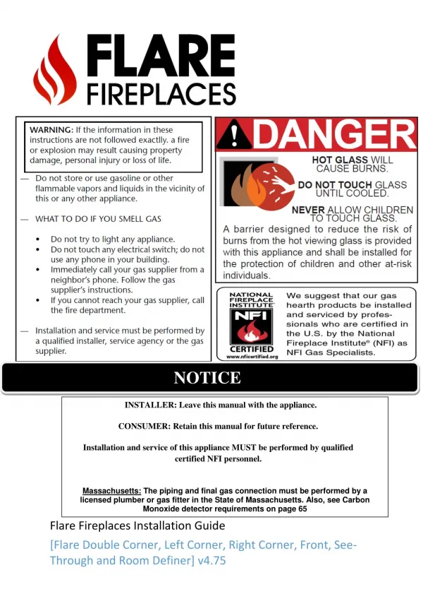
NOTICE INSTALLER: Leave this manual with the appliance. CONSUMER: Retain this manual for future reference. Installation and service of this appliance MUST be performed by qualified certified NFI personnel. Massachusetts: The piping and final gas connection must be performed by a licensed plumber or gas fitter in the State of Massachusetts. Also, see Carbon Monoxide detector requirements on page 65 Flare Fireplaces Installation Guide [Flare Double Corner, Left Corner, Right Corner, Front, See- Through and Room Definer] v4.75
TABLE OF CONTENTS SAFETY INFO AND WARNINGS..................................................................................................................................... 5 FLARE FIREPLACES – FRAMELESS IN EVERY WAY ......................................................................................................... 7 SAFETY ............................................................................................................................................................................. 7 CSA CERTIFICATION ..................................................................................................................................................... 7 MANUAL MODEL LIST & INFORMATION ...................................................................................................................... 8 FIREPLACE OPERATION................................................................................................................................................ 9 REMOTE CONTROL INSTRUCTIONS ............................................................................................................................................ 9 RECEIVER AND REMOTE BATTERIES ......................................................................................................................................... 13 PAIRING REMOTE WITH FIREPLACE RECEIVER ............................................................................................................................ 13 WALL SWITCH – OPTIONAL ................................................................................................................................................... 14 MEDIA ARRANGEMENTS ....................................................................................................................................................... 15 SAFETY SCREEN REMOVAL..................................................................................................................................................... 16 EXTERNAL GLASS - FIRST TIME REMOVAL – DOUBLE GLASS FIREPLACE ............................................................................................ 17 EXTERNAL GLASS REMOVAL – DOUBLE GLASS FIREPLACE ............................................................................................................. 18 INTERNAL GLASS REMOVAL ................................................................................................................................................... 19 REFLECTIVE BACK INSTALL .................................................................................................................................................... 21 INSTALLATION STEPS ................................................................................................................................................. 22 INSTALLATION PREPARATION ................................................................................................................................... 23 FIREPLACE UNPACKING ........................................................................................................................................................ 23 FIREPLACE TELESCOPIC LEGS SETUP ......................................................................................................................................... 24 leg setup for front and see through units .................................................................................................................. 25 leg setup for corner units .......................................................................................................................................... 26 UNPACKING CONTROL UNIT AND ACCESSORIES .......................................................................................................................... 27 FIREPLACE POSITIONING ....................................................................................................................................................... 29 FIREPLACE ELECTRICAL CONNECTION ....................................................................................................................................... 30 LED LIGHTS ................................................................................................................................................................ 33 LED LIGHT INSTALL AND POWER ............................................................................................................................................. 34 VENT TERMINATION ................................................................................................................................................. 35 VENT AND FIREPLACE SIZE ..................................................................................................................................................... 36 MINIMUM COMBUSTIBLE CLEARANCES FROM VENT ................................................................................................................... 36 VENT RESTRICTOR SETUP ...................................................................................................................................................... 41 CHIMNEY PATH INSTALLATION AND PLANNING .......................................................................................................................... 42 FLARE 25 .................................................................................................................................................................... 43 FLARE 30H ................................................................................................................................................................. 45 FLARE 45/45H ............................................................................................................................................................ 47 FLARE 50/50H ............................................................................................................................................................ 49 FLARE 60/60H ............................................................................................................................................................ 51 FLARE 70/70H ............................................................................................................................................................ 53 2 | P a g e
FLARE 80/80H ............................................................................................................................................................ 55 FLARE 100/100H ........................................................................................................................................................ 57 POWER VENTING ................................................................................................................................................................ 59 GAS INSTALLATION ................................................................................................................................................... 62 GENERAL .......................................................................................................................................................................... 62 ORIFICE SIZE ...................................................................................................................................................................... 63 GAS VALVE ACCESS DOOR ..................................................................................................................................................... 64 COMMONWEALTH OF MASSACHUSETTS .................................................................................................................................. 65 FLARE FIREPLACES - DOUBLE GLASS .......................................................................................................................... 66 OVERVIEW ........................................................................................................................................................................ 66 DOUBLE GLASS - INSTRUCTIONS ............................................................................................................................................. 66 Power requirements .................................................................................................................................................. 67 TELEVISION MOUNTING ABOVE FIREPLACE ............................................................................................................... 67 TV INSTALL – FLAT EXAMPLE ................................................................................................................................................. 68 TV INSTALL – L TYPE EXAMPLE ............................................................................................................................................... 69 TV INSTALL RECESS –45 DGREE ELBOW ON TOP OF THE UNIT....................................................................................................... 70 TV INSTALL WITHOUT RECESS – MANTEL REQUIREMENTS ............................................................................................................ 71 CLEARANCES ............................................................................................................................................................. 72 GENERAL INFORMATION AND STEPS ........................................................................................................................................ 72 CLEARANCES SPECIFICATION .................................................................................................................................................. 76 MANTEL CLEARANCE ........................................................................................................................................................... 77 HEAT RELEASES .................................................................................................................................................................. 78 AIR INTAKE ........................................................................................................................................................................ 78 Release and intake example ...................................................................................................................................... 78 EXAMPLES OF HEAT RELEASES ................................................................................................................................................ 79 FLARE FRONT, SEE THROUGH, AND CORNER FIREPLACE CLEARANCE ............................................................................................... 80 Flat – side and isometric view ................................................................................................................................... 80 L shape – side and isometric view ............................................................................................................................. 82 FLARE ROOM DEFINER FIREPLACE CLEARANCE ........................................................................................................................... 84 Flat – side and isometric view ................................................................................................................................... 84 L shape – side and isometric view ............................................................................................................................. 86 INDOOR/OUUTDOOR KIT .......................................................................................................................................... 88 APPLIANCE LOCATION ......................................................................................................................................................... 88 PRODUCT DIMENSIONS & SPECIFICATIONS ............................................................................................................... 91 BURNER DIMENSIONS .......................................................................................................................................................... 91 HOME AUTOMATION ................................................................................................................................................ 92 ELECTRIC AND CONTROL ........................................................................................................................................... 93 ELECTRIC DIAGRAM ............................................................................................................................................................. 93 DIAGRAM – DOUBLE GLASS AND PV ........................................................................................................................................ 94 ELECTRIC DIAGRAM – PV SYSTEM ........................................................................................................................................... 95 3 | P a g e
REPLACEMENT PARTS ............................................................................................................................................... 96 MAINTENANCE .......................................................................................................................................................... 97 APPENDIX.................................................................................................................................................................. 99 MAINTENANCE LOG ............................................................................................................................................................. 99 WARRANTY POLICY............................................................................................................................................................ 100 4 | P a g e
SAFETY INFO AND WARNINGS 5 | P a g e
FLARE FIREPLACES – FRAMELESS IN EVERY WAY Flare Fireplaces is where innovation, quality and luxury come together to form new ideas. By combining superior raw materials, contemporary design, creative technology and a frameless way of thinking, we have created a full line of direct-vent fireplaces that are luxurious, simple to operate, and efficient. Our Fireplaces are distinguished by their clean design, superior build quality and unique features. SAFETY CSA CERTIFICATION All our fireplaces are tested and have been certified to meet stringent CSA guidelines, ensuring optimum quality, safety and efficiency. All our fireplaces have been certified and tested to work with Natural Gas or Propane. Certification Information: ANSI Z21.88/CSA 2.33-2014- Vented Gas Fireplace Heaters CSA CLASSES: CLASS 2901 84 / CLASS 2901 04 All fireplaces are rated for commercial and residential use. 7 | P a g e
MANUAL MODEL LIST & INFORMATION The Following manual should be used for the following Flare Fireplaces Models: • • • • • Flare Front 25-100 “ Flare See-Through 25-100” Flare Corner Right & Left 25-100” Flare Double Corner 25-100” Flare Room Definer 30-100” All models share the same gas valve system, remote, gas connection, and glass type, simplifying installation and operation. All warnings and instructions apply to all models. Refer to the model name for specific model, clearance and installation information. Flare Fireplaces should only be connected to M&G DuraVent 4x6 or 5x8 venting system. Refer to the specific appliance model and size to determine vent size (Gas specification table) and chimney pathway requirements (Chimney path installation & planning table). For detailed chimney installation information please use the M&G DuraVent direct vent installation manual: http://www.duravent.com This product is listed to ANSI standards for “Vented Gas Fireplace Heaters” and applicable sections of “Gas Burning Heating Appliances for Manufactured Homes and Recreational Vehicles”, and “Gas Fired Appliances for Use at High Altitudes”. Installation MUST comply with local, regional, state and national codes and regulations. Consult insurance carrier, local building inspector, fire officials or authorities having jurisdiction over restrictions, installation inspection and permits. This installation must conform to local codes. In the absence of local codes, you must comply with the National Fuel Gas Code, ANSI Z223.1-latest edition in the U.S.A. and the CAN/CGA B149 Installation Codes in Canada. Improper installation, adjustment, alteration, service or maintenance can cause injury or property damage. For assistance or additional information, consult a qualified service technician, service agency or your dealer. 8 | P a g e
FIREPLACE OPERATION REMOTE CONTROL INSTRUCTIONS 9 | P a g e
RECEIVER AND REMOTE BATTERIES Batteries – Remote • • • 2 x AAA (alkaline recommended). Low battery indicator on handsets with display. Battery replacement is recommended after 2 years. Batteries – Receiver • • • • 4 x 1.5 V “AA” (alkaline ONLY). Low battery indication: frequent beeps for 3 seconds when motor turns. An AC Mains Adapter may be connected in addition to batteries. Without using a mains AC adapter, battery replacement is recommended at the beginning of each heating season as part of the yearly service check. CAUTION, DO NOT USE a screwdriver or other metallic object to remove the batteries from the battery box! This could cause a short circuit to the system. PAIRING REMOTE WITH FIREPLACE RECEIVER Your remote will come paired with the fireplace receiver to allow operation out of the box. In the event of remote or receiver replacement use the following procedure to pair the remote with the receiver: • Press and hold the receiver’s reset button (see figure 21) until you hear two (2) beeps. The first beep is short and the second beep is long. After the second beep, release the reset button. Within the subsequent 20 seconds, press the (Down Arrow) button on the handset until you hear two additional short beeps confirming the code is set. If you hear one long beep, this indicates the code learning sequence has failed or the wiring is incorrect. • 13 | P a g e
WALL SWITCH – OPTIONAL The Wall Switch can be used to control your fireplace. Following operation can be done from the wall switch: • • • • Turn On fireplace. Turn Off fireplace. Increase the flame height. Decrease the flame height. Note that the thermostat and programming functions are not available with the wall switch. The fireplace receiver will respond to both, the wall switch or remote commands regardless of what was used first or what was used to turn the system on. The Wall switch is an optional item and is equipped with 20 feet cable. 14 | P a g e
MEDIA ARRANGEMENTS Flare Fireplace can be equipped with different media types. Follow the instruction below for information on how to add and arrange media in your Fireplace: • Do not place any type of media on the pilot or in front of the pilot. Keep 1” distance from the pilot to allow correct operation of the pilot. Media can be put over the Flare burner. Avoid placing media over the main burner ports as it may disrupt flame in case of a clogged port. If using media that was not supplied by Flare Fireplace, make sure that the media is certified/suitable to be used in direct vent gas fireplaces. Keep the pilot front cover view open in order to be able to view the pilot spark and flame from outside. Fireglass: a.¼” or ½” fireglass may be used. b.When the fireplace window is open and media is placed, make sure fireglass does not fall on the ceramic glass lower frame as that may cause breakage when putting back the ceramic glass. c.Make sure pilot is clear of any fireglass particles. d.Flare fireglass can be put safely in to the firebox. Avoid overloading the burner with fireglass, specifically over the main burners ports. Maintain minimum distance of ¼” from media to the fireplace glass panels. Use the manual for instruction on how to remove and place back the fireplace glass in order to put or arrange the fireplace media. • • • • • • Ceramic Pebbles Fireglass CHOKING HAZARD! Ensure that the fireplace area is clear of fire glass particles as these could be ingested by small children. Vacuum area after installation. 15 | P a g e
SAFETY SCREEN REMOVAL Follow the instruction below for safety screen removal. The barrier is designed to reduce the risk of burns from the hot viewing glass and is provided with this appliance. It must remain installed for the protection of children and other at-risk individuals. Do NOT operate the fireplace without the safety screen barrier. Front, See Through, and Corner Units • • • Safety screen removal requires no tools. Push the top frame of the screen up until it clears the bottom of the opening. Tilt the bottom of the screen out and pull down so the top frame clears the opening. 16 | P a g e
EXTERNAL GLASS - FIRST TIME REMOVAL – DOUBLE GLASS FIREPLACE Note: Suction cups are needed to remove the glass. • This step is only applicable for first time external glass removal during installation, before the wall has been finished around the fireplace. Remove and discard glass locking stainless screws from the top and bottom fireplace frame. When removing the external glass from a double glass unit verify the lock screws have been removed and discarded. • • The lock screws are only needed for shipping. Please discard once fireplace is unpacked and placed in installation site. It is not possible to remove the glass if lock screws are not removed. It is not possible to remove the lock screws after fireplace wall has been finished. 17 | P a g e
EXTERNAL GLASS REMOVAL – DOUBLE GLASS FIREPLACE Follow the procedure below to remove and install back the fireplace external glass (double glass fireplace configuration). Note: Suction cups are needed to remove the glass. Warning! Turn off the fireplace, and allow time for the unit to cool before proceeding. Caution: The glass is very fragile, and should be handled with care. Warning! Double glass fireplace should NOT be operated without the external glass • • • • • Confirm lock screws have been removed during install (should be done once, during install only). Attach glass suction cups to the glass. Use more than one suction cup if needed (any unit above 45”). Using suction cups, slightly push in the external glass top edge. Once glass has been pushed, slightly lift the glass to clear bottom part of the glass. Remove the glass and place in a secure location. Install back external glass • • • • • Attach glass suction cups to the glass. Use more than one suction cup if needed (any unit above 45”) Place upper edge of the glass in position and push latching trim. Once trim has been pushed in, slide glass top in position. Title in bottom edge of the glass in position as you are lifting the glass up. Glass is now secure in place. No bolts are need to lock the glass. 18 | P a g e
INTERNAL GLASS REMOVAL Follow the procedure below to remove and install back the fireplace internal ceramic glass (double glass fireplace configuration). Note: Suction cups are needed to remove the glass. Warning! Turn off the fireplace, and allow time for the unit to cool before attempting to remove the glass. CAUTION: The ceramic glass is very fragile, and should be handled with care. CAUTION: Do not operate the appliance with glass removed, cracked or broken. Replacement of the panel(s) should be done by a licensed or qualified service person Step 1 – Attach glass suction cups to the glass. Remove the glass lower magnetic trim. Place the trims in a secure place. Any unit above 45” requires 2 suction cups to hold the glass. Step 2 – Release the glass lower trim. The lower trim bolts can be released by hand and should not require any tools. once bolts are released remove lower glass holder trim. Step 3 – Hold the glass suction cup and hand release trim bolt on the top. The trim does not need to be removed and will only open to allow a gap for glass removal. Step 4 – Push the glass up and clear it from the bottom as showing When putting back the glass, DO NOT overtighten the bolts or glass may break Step 1 Step 2 19 | P a g e
Step 3 Step 4-1 Step 4-2 When putting back the glass, DO NOT overtighten the bolts or glass may break • • Use step 4 – 1 for putting the glass back. Glass trim screws should be closed hand-tight. DO NOT overtighten the bolts or glass may break. 20 | P a g e
REFLECTIVE BACK INSTALL The Flare Fireplace can be ordered with reflective ceramic glass at the back. The ceramic glass is tinted black to create a reflection when the fireplace is running. The ceramic glass will enhance and protect the fireplace look and is very easy to clean. The reflective back is shipped outside the unit. It should be mounted at the back of the fireplace, placed in the gap between the firebed (shown yellow below) and held by the top mounting bracket (red). 21 | P a g e
INSTALLATION STEPS 1.Prior to starting the installation, make sure you read and understand all WARNING information in the manual. Do not start the installation if you are not clear about any of the installation related subjects. 2.Determine the following: • The vent system configuration to be used based on the fireplace location. Follow the manual venting section (Chimney path installation & planning tables) to determine the venting requirements and setting. Note: Venting requirements are model specific. Note: Make sure the vent requirements are supported by the Flare manual and installation instruction. • Clearance requirements from combustible and non-combustible materials. Follow the clearance instruction and example in the manual. Note: Clearance instructions and examples are model specific. • Gas supply piping. • Confirm if the fireplace is going to operate using Natural Gas (NG) or Propane (LPG). Use the attached product label to confirm the fireplace is set for the expected gas type. • Electrical wiring requirements. • Framing and finishing details. 3.Unpack the fireplace box, adjust telescopic legs and place in the upright position. Follow instruction for fireplace unpacking. 4.Put the Fireplace in the desired location. Verify clearance to non-combustible and combustible materials. Follow the clearance instruction and example in the manual. 5.For LED units, connect LED system and test LED. 6.Attach the unit back bracket to the wall framing. 7.For double glass units only: remove glass locking screws and discard. 8.Adjust Fireplace vent restrictor based on vent configuration and planning guide. Document vent restrictor setup here: ___________________________. 9.Connect vent system to the Fireplace. 10.Connect gas (Gas connection section) line to the Fireplace and verify gas inlet and outlet pressure. Measure and document gas pressure here: Inlet _______ W.C. 11.Confirm if adjustments for high altitude are needed (Installation at above 2000 Ft from sea level). 12.Connect electrical wiring for applicable units. 13.Insert and place Fireplace media. Use media arrangement guide from the manual. 14.Verification of: • Ignition and pilot system. • Burning and flame. 15.Complete framing and wall covers. Read all the instructions before starting the installation. Follow these instructions carefully during the installation to ensure maximum safety and benefit. Follow the Steps above to insure proper installation of the Gas appliance. WARNING! Risk of Fire or Explosion! Damaged parts could impair safe operation. DO NOT install damaged, incomplete or substitute components. 22 | P a g e
INSTALLATION PREPARATION FIREPLACE UNPACKING Follow the instructions below for unpacking the unit: • Check the packing and confirm there is no external damage. If damage exists, please notify Flare Fireplaces immediately. • Remove the top wood studs and pull the external carton box up. • Please do not remove the blue wrap completely at this stage. • Leave the fireplace placed on the pallet for the next step: Fireplace legs setup. 23 | P a g e
FIREPLACE TELESCOPIC LEGS SETUP The fireplace legs will need to be set up once box is removed. The legs can be configured so that the bottom of the glass will be between 10”-19” above the floor. This means the bottom of the fireplace will be 4”-13” above the floor. Follow the steps below for telescopic legs setup prior to final positioning of the fireplace. On Corner units (Flare-RC/LC/DC/RD) front legs will need to be assembled. Fireplace must NOT be installed without telescopic legs extracted to a minimum of 3”. Installing fireplace without telescopic legs is a fire hazard. Installing the Fireplace without legs (sitting on the fireplace frame) may bend the frame & cause glass breakage. Fine Tuning After extending the legs to the desired length, use the wrench included to fine tune the feet so that the fireplace is level. Note that the feet are intended for minimal adjustments and not to be extended completely for extra height. Doing so will make the fireplace unstable. 24 | P a g e
LEG SETUP FOR FRONT AND SEE THROUGH UNITS • • Step 1 - Release the 3 screws from the leg. Step 2 –Extend the telescopic leg to the desired length, minimum 4” (That will set the fireplace 10” from the bottom of the glass to the floor). Step 3 – Retighten the three screws to secure the telescopic leg in position. Note that the top screw inserts into the holes only for alignment. The two bottom screws tighten down on the legs but are not inserted into holes. Step 4 – Repeat Steps 1-3 for each on the fireplace so that they are all extended to the same length. Step 5 – Stand the fireplace up and fine tune the feet with the wrench included so the fireplace is level. Open the screws to raise the fireplace. Close the screws to lower the fireplace. Step 1 • • • Step 2 Step 3 25 | P a g e
LEG SETUP FOR CORNER UNITS Included are 4 screws, 2 adjustable legs, 1 foot for fine tuning, and 1 special wrench for adjusting the feet while the fireplace is standing. • First, identify the correct order to connect the legs. The first adjustable leg that attaches to the fireplace has rivnuts as seen in the image below. The second adjustable leg has a place for the foot to be screwed in on the bottom as seen in the images below. Next, determine which holes to insert the 4 screws so that the fireplace will stand at the desired height after the foot for fine tuning is also screwed in. Insert the 4 screws into the holes and rivnuts beneath and tighten. Screw in the foot so that it can later be adjusted to slightly raise or lower the fireplace. Configure remaining legs to the same height. • • • Stand the fireplace up and fine tune the feet with the wrench provided so the fireplace is level. Open the screws to raise the fireplace. Close the screws to lower the fireplace. • 26 | P a g e
UNPACKING CONTROL UNIT AND ACCESSORIES Unpack the gas valve, receiver, control module (for double glass units) and accessories (remote, power adapter & wall switch). • • Place accessories (white bag) in a secure location. The control unit (gas valve and receiver) is attached to the fireplace on an “umbilical cord”. Once fireplace is moved to its final location the control unit can be put close to the service access door. 27 | P a g e
Gas valve and receiver: Control module for double glass units. Either: Or: 28 | P a g e
FIREPLACE POSITIONING Once Fireplace has been set to the upright position, it can be moved to its final installation location. • • • Make sure the control unit is secure and not dragging on the floor during transport and positioning. Unit should remain on the pallet during transport inside the site location. When positioning the fireplace, take consideration of clearance requirements and framing. Use the manual clearance guide for more details. Attach the fireplace top brackets to the metal stud in the back to secure the fireplace in place. The bracket length can be adjusted by releasing the screws on the top. • Fireplace should remain on the wood pallet when carried to final installation location. Do not attempt to use a pallet jack or any other moving tools if the unit has been removed from the wood pallet as it may harm the fireplace components under the unit. Make sure to use only non combustible material in case top the bracket need to be extended in order to connect to the back or sides. 29 | P a g e
FIREPLACE ELECTRICAL CONNECTION The Flare Fireplaces line uses electronic pilot ignition and requires a power source to operate with the following options: Safety screen units • • Option 1 - Battery powered: 4 x AA Alkaline battery installed inside the fireplace receiver. Option 2 - External optional power adapter – Input 110V – Output 6V. Note: It is not recommended to use both AA batteries and power adapter. Power option 1 Power option 2 • The Flare Fireplace gas valve and control system is on an “Umbilical cord” that can be stretched up to 50 inches from the middle of the fireplace. Make sure your power outlets are located near the selected location for the Flare gas/led systems. LED connection will require an additional 110V power source. Please review LED connection section of the document. • 30 | P a g e
Double glass unit Connect the Control Board as labeled on the side or as shown in the picture below. Connect items 1-5 on the Control Module with their corresponding plugs coming from the fans and receiver. • • • • • 1 – Fan Harness 2 – Fans Ground 3 – Power 110V 15A – Provides power to the Flare Control Module, Fans, Receiver, and LEDs. 4 – Connection to the receiver 5 – Receiver Power and Relay Cable – 6V DC providing power to receiver. Relay cable connects to AUX Port. 31 | P a g e
NOTE: Double glass fireplace should not be installed with AA batteries inside the receiver. The electrical line to the fireplace must supply 120 Volts, 60 Hz, and 15 Amps (maximum draw). A dedicated circuit for the fireplace is recommended. The Flare Fireplace gas valve and control system is on an “umbilical cord” that can be stretched up to 50 inches from the middle of the fireplace. Make sure power outlets are located near the selected location for the Flare gas/led systems. Consider the location of a 10x10 inch access door. Make sure the household breaker is shut off prior to working on any electrical connection. Turn the breaker ON only after all wiring is in place (Power vent, LED and Fireplace, etc). The appliance, when installed, must be electrically grounded in accordance with local codes or, in the absence of local codes, with the National Electrical Code, ANSI/NFPA 70, or the Canadian Electrical Code, CSA C22.1. See next section for LED power connection. • • • • • • • 32 | P a g e
LED LIGHTS The Flare Fireplaces can be ordered with optional multi-color interior RGB LED lighting or warm white LED. The lights allow perfect flames to be viewed across a bed of illuminated crushed glass. RGB LED– Multi color option controlled by a remote control for color selection. Once the color has been selected by the operator, next time LED is turn use, system will remember and maintain color selected. Warm white– Single warm white color to complement the flame color. LED Operation: Option 1 • LED power is connected to the Flare control system (Labeled in picture above as LED Power Outlet, and below as Connection C) LED will turn On and Off with the fireplace, controlled by the fireplace remote or wall switch. Color control can be done by the LED remote. Once a color is selected, the LED remote can be stored away. LED to be switched Off when fireplace is turned off. LED cannot be switched On when fireplace is off. The LED remote can be stored away once color is selected. • • • • • • Option 2 • • • LED connected to independent power source or home automation system. LED can be turn ON/OFF from LED remote, independent from the fireplace. LED can be turned on, even when fireplace is off. 33 | P a g e
LED LIGHT INSTALL AND POWER It is best if LED lights are connected and tested during the initial stages of installation in order to allow easy access under the unit (before the wall finishing material is done). Testing the LED light requires a 110V power source. Installation steps: 1.Remove all LED components from the shipping bag. 2.Connect LED connectors (points A) to the fireplace using the quick connect connectors. 3.Connect LED control system to the power supply (point B) 4.Connect LED Power supply to an external power source (point C). Do not connect the LED to the Flare control LED plug at this point. Use the LED remote to turn the LED on the LED system. Once testing is done, connect the LED power adapter to final power source (Point C), Option 1 or Option 2 as detailed in the previous page. Power outlet on the Flare control is optional for LED ONLY 34 | P a g e
VENT TERMINATION Framing for vents in combustible walls and ceilings: When passing through combustible walls and ceilings, framing will depend on the type of vent installation -- horizontal or vertical. Ensure that the insulation is kept clear of the vent pipe using either a wall thimble or an attic insulation shield. Follow the installation instructions supplied with the individual venting components. These instructions should be used as a guideline and do not supersede local codes in any way. Install venting according to local codes, these instructions, the current National Fuel Gas Code (ANSI-Z223.1) in the USA or the current standards of CAN/CSA-B149.1 in Canada. Approved Pipe - This appliance is approved for use with M&G DuraVent venting systems ONLY. DO NOT mix pipe, fittings or joining methods from different manufacturers. For detailed chimney installation information please use the M&G DuraVent direct vent installation manual: http://www.duravent.com Instructions • Where a vent pipe passes through a floor or ceiling, a ceiling firestop MUST be used to retain insulation and maintain proper clearances. Use roof support brackets where needed. Install the first section of vent pipe into the collar on top of the fireplace. Connections between each vent system component must be tightly joined and secured. Follow the vent manufacture instruction for information on how to seal and secure vent and vent connections. Horizontal runs of vent pipe must be supported to prevent any downward sags. Horizontal pipe sections should be supported at least every 4 feet. Wall Straps can be used for this purpose. When installing the vent pipe, make sure that the vent pipe is supported by the structural/frame surrounding and not by fireplace. • • • • Follow the vent manufacture instruction for information on how install, seal and secure vent and vent connections. WARNING! DO NOT pack insulation around the vent. Insulation must be kept back from the pipe to prevent overheating. ALWAYS maintain specified clearances around venting and firestop systems. Install wall shield and ceiling firestops as specified. 35 | P a g e
VENT AND FIREPLACE SIZE Size Flare 25 Flare 30 Flare 45* Flare 50 Flare 60 Flare 70 Flare 80 Flare 100 Vent Size 4x6 4x6 5x8 Or 4x6 * 5x8 5x8 5x8 5x8 5x8 *Flare-RD-45 is shipped with 5x8 vent. All other Flare 45 are shipped out with 4x6 vent MINIMUM COMBUSTIBLE CLEARANCES FROM VENT • HORIZONTAL VENT CLEARANCES: A minimum clearance of 3 inches (76mm) to the top and 1 inches (51mm) to the sides and bottom of the vent pipe on all horizontal runs to combustibles is required. • VERTICAL VENT CLEARANCES: A minimum of 1 inches (25mm) all around the vent pipe on all vertical runs to combustibles is required except for clearances in appliance enclosures. • Horizontal vents have a minimum 1/4 inch (6mm) rise per 1 foot towards the termination. Frame cutout table taken from the DuraVent installation manual . 36 | P a g e
VERTICAL TERMINATION See the table on the previous page for minimum cutout dimensions or frame openings around wall venting. Make sure clearances to combustible material are maintained based on vent part used. Note: size of vents depends upon specific fireplace and cutout sizes vary according to the DuraVent part number used. Minimum height from roof lowest discharge opening Vertical Vent Termination Opening/Framing will depend on the part used. See table above or vent installation manual. • Minimum 24” horizontal clearance to any surface (such as an exterior wall) for vertical terminations 37 | P a g e
Multiple terminations HORIZONTAL TERMINATION A minimum distance of 18 inches should be kept between multiple horizontal terminations. See the table on page 32 for minimum cutout dimensions or frame openings around wall venting. Make sure clearances to combustible material are maintained based on vent part used. Note: size of vents depends upon specific fireplace and cutout sizes vary per the DuraVent part number used. 38 | P a g e
Vent termination clearances A *12 inches (30 cm) min. Clearances above grade, veranda, porch, deck, or balcony B *12 inches (30 cm) min. Clearance to window or door that may be opened Clearance to permanently closed window recommended to prevent condensation on window C 12 inches (30 cm) min. 30 inches (76 cm) min. for Flare units 80” and 100” Vertical clearance to ventilated soffit located above the terminal within a horizontal distance of 2 feet (60 cm) from the edge of the terminal D 18 inches (46 cm) min. for Flare units 70” and below (vinyl surfaces require 24 inches (61 cm) min.) 30 inches (76 cm) min. for Flare units 80” and 100” E Clearance to unventilated soffit. 18 inches (46 cm) min. for Flare units 70” and below (vinyl surfaces require 24 inches (61 cm) min.) F 6 inches (15 cm) min. Clearance to outside corner G 6 inches (15 cm) min. Clearance to inside corner *Not to be installed above a meter/regulator assembly within 3 feet (90 cm) horizontally from the center-line of the regulator H 3 feet (90 cm) min. I 3 feet (90 cm) min. Clearance to service regulator vent outlet 39 | P a g e
Clearance to non-mechanical air supply inlet to building or the combustion air inlet to any other appliance J *12 inches (30 cm) min. K *6 feet (1.8 m) min. Clearance to a mechanical air supply inlet ^ Clearance above paved side-walk or a paved driveway located on public property L *7 feet (2.1 m) min. M **30 inches (76 cm) min. Clearance under veranda, porch, deck, or balcony ^ a vent shall not terminate directly above a side-walk or paved driveway which is located between two single family dwellings and serves both dwellings* ** only permitted if veranda, porch, deck, or balcony is fully open on a minimum of 2 sides beneath the door* * as specied in CGA B149 Installation Codes, Note: local Codes or Regulation may require different clearances * for U.S.A. Installations follow the current National Fuel Gas Code, ANSI Z223.1 ***Horizontal vent termination minimum clearance to adjacent structure or fence is 48”. **** Minimum 24” horizontal clearance to any surface (such as an exterior wall) for vertical terminations 40 | P a g e
VENT RESTRICTOR SETUP Flare Fireplace direct vent system is equipped with a vent restrictor. Use Chimney Path Installation and Planning on the next page to determine the right vent restrictor setup for your installation. Vent restrictor changes and setup should only be done by a certified installer. • • • • • The unit leaves the factory with the vent restrictor open. The vent restrictor is adjusted using a 10mm wrench below the front upper frame. The vent restrictor setting is from 1 (minimum restriction) to 6 (maximum restriction). The installer will document the restrictor setting in the end of the installation. Use the vent planning guide and table to determine the restrictor setting. Signs the vent restrictor needs to be adjusted: Vent restrictor should be opened if the flame has the following characteristics: • Flame is excessively tall and lifting. • Flame lacks movement. Vent restrictor should be closed if the flame has the following characteristics: • Flame height is low. • Flame has excessive movement Document any change to the restrictor setting. Contact Flare Fireplaces for support if needed. 41 | P a g e
CHIMNEY PATH INSTALLATION AND PLANNING Before vent installation, the installer should read these instructions to ensure that the proper vent configuration has been selected. General instructions • Diagonal runs have both vertical and horizontal vent aspects when calculating the effects. Use the rise for the vertical aspect and the run for the horizontal aspect. • Various combinations of vent runs may be used. Refer to the tables below based on Fireplace size. Use the attached example for clarification on how to use the table. • The numbers in the table represent the restrictor setting based on the vent path. • Symbol “x” in the table means the path is not allowed. • Setting the restrictor to 1 means there is no restriction. • Numbers in the table represent the restrictor setting to be set. • Document the restrictor setting configuration prior to leaving the installation site. • The tables apply to both NG (Natural Gas) and LP (Propane). • Minimum 3 ft vertical run (A) required before any bend or turn (See Flare Front and Flare See Through exception). • A maximum of four 90º vent elbows are allowed in the vent run. Any configuration with more than 4 elbows requires vent review and approval from Flare Fireplaces. • Two 45º elbows may be used in place of one 90º elbow. • The tables represent the manufacturer’s guideline based on testing and design. Additional external factors may affect the restrictor choice needed. If flame appears to be not typical, please contact Flare Fireplaces for restrictor size recommendations. • Use the empty table in the page below to document and calculate the installation vent path. • Any venting pathway that does not appear the tables below require approval from Flare Fireplaces. For optimum performance and flame appearance, keep the vent length to a minimum and limit the number of elbows. 42 | P a g e
FLARE 25 Suitable for all Flare 25 appliances: Flare Front 25, Flare See-Through 25, Flare Double Corner 25, Flare Left Corner 25, Flare Right Corner 25. Length X - Effective Horizontal Length Y - Effective Vertical Length Y Axis Parameters A – First Flue length (1 m / 3 ft. min) B – Vertical Flue length C – Roof Terminal = 0.5 m / 1.5 ft. H – Small Elbow (45°) = 0.3 m / 1 ft. X Axis Parameters D – Horizontal Flue length E – Elbow (90°) = 1 m / 3 ft. F – Elbow (lying 90°) = 2 m / 6 ft. G – Wall Terminal = 1 m / 3 ft. Adjust Restrictor level using Table 1: 1 – 6: adjust your restrictor level according to the table. X: Not Eligible chimney path! Plan a different chimney path. Restrictor level (Table 1): Y/X X - Effective Horizontal Length 3 / 10' 13' 17' 20' 1 1 1 1 2 2 1 1 2 1 1 1 1 1 1 1 1 1 1 1 1 1 1 1 1 1 1 1 1 1 1 1 1 1 1 1 1 1 1 1 1 1 1 1 1 1 1 1 1 1 1 1 1 1 1 1 1 1 1 1 1 / 3' 2 2 2 2 1 1 1 1 1 1 1 1 1 1 1 2 / 6' 1 2 2 1 1 1 1 1 1 1 1 1 1 1 1 4 / 5 / 6 / 7 / 23' 1 1 1 1 1 1 1 1 1 1 1 1 1 1 1 8 / 26' 1 1 1 1 1 1 1 1 1 1 x x x x x 9 / 30' 1 1 1 1 1 1 1 1 1 x x x x x x 10 / 33' x 1 1 1 1 1 1 1 x x x x x x x 11 / 36' x 1 1 1 1 1 1 x x x x x x x x 12 / 39' x 1 1 1 1 1 1 x x x x x x x x m / ft. 0 Y - Effective Vertical Length 1 / 3' 2 / 6' 3 / 10' 4 / 13' 5 / 16' 6 / 19' 7 / 23' 8 / 26' 9 / 30' 10 / 33' 11 / 36' 12 / 39' 13 / 43' 14 / 46' 15 / 50' 3 4 4 3 2 2 2 1 1 1 1 1 1 1 1 43 | P a g e
FLARE 25H – CHIMNEY PATHS EXAMPLES Parameters Calculation X - Effective Horizontal Length 6.5m / 19.5ft. Y - Effective Vertical Length 7.6m / 23ft. Restrictor Level By Table 1: Level 1 Y Axis Parameters A – First Flue length (1 m / 3 ft. min) 1m / 3ft. B – Vertical Flue length 5.5m / 16.5ft. C – Roof Terminal = 0.5 m / 1.5 ft. 0.5m / 1.5ft. H – Small Elbow (45°) = 0.3 m / 1 ft. 0.6m / 2ft. X Axis Parameters D – Horizontal Flue length 4.5m / 13.5ft. E – Elbow (90°) = 1 m / 3 ft. 2m / 6ft. F – Elbow (lying 90°) = 2 m / 6 ft. 0 G – Wall Terminal = 1 m / 3 ft. 0 Parameters Calculation X - Effective Horizontal Length 9m / 27ft. Y - Effective Vertical Length 4m / 12ft. Restrictor Level By Table 1: Level 1 Y Axis Parameters A – First Flue length (1 m / 3 ft. min) 1m / 3ft. B – Vertical Flue length 3m / 9ft. C – Roof Terminal = 0.5 m / 1.5 ft. 0 H – Small Elbow (45°) = 0.3 m / 1 ft. 0 X Axis Parameters D – Horizontal Flue length 3m / 9ft. E – Elbow (90°) = 1 m / 3 ft. 3m / 9ft. F – Elbow (lying 90°) = 2 m / 6 ft. 2m / 6ft. G – Wall Terminal = 1 m / 3 ft. 1m / 3ft. 44 | P a g e
FLARE 30H Suitable for all Flare 30 appliances: Flare Front 30, Flare See-Through 30, Flare Double Corner 30, Flare Left Corner 30, Flare Right Corner 30, Flare Room Definer 30. Length X - Effective Horizontal Length Y - Effective Vertical Length Y Axis Parameters A – First Flue length (1 m / 3 ft. min) B – Vertical Flue length C – Roof Terminal = 0.5 m / 1.5 ft. H – Small Elbow (45°) = 0.3 m / 1 ft. X Axis Parameters D – Horizontal Flue length E – Elbow (90°) = 1 m / 3 ft. F – Elbow (lying 90°) = 2 m / 6 ft. G – Wall Terminal = 1 m / 3 ft. Adjust Restrictor level using Table 1: 1 – 6: adjust your restrictor level according to table. X: Not Eligible chimney path! Plan a different chimney path. Restrictor level (Table 1): Y / X X - Effective Horizontal Length 3 / 10' 13' 17' 20' 1 1 1 1 1 1 1 1 1 1 1 1 1 1 1 1 1 1 1 1 1 1 1 1 1 1 1 1 1 1 1 1 1 1 1 1 1 1 1 1 1 1 1 x 1 1 1 x 1 1 1 x 1 1 1 x 1 1 1 x 1 / 3' 2 2 2 2 1 1 1 1 1 1 1 1 1 1 1 2 / 6' 1 2 2 1 1 1 1 1 1 1 1 1 1 1 1 4 / 5 / 6 / 7 / 23' 1 1 1 1 1 1 1 1 1 1 x x x x x 8 / 26' 1 1 1 1 1 1 1 1 1 1 x x x x x 9 / 30' x 1 1 1 1 1 1 1 x x x x x x x 10 / 33' x 1 1 1 1 1 1 1 x x x x x x x 11 / 36' x 1 1 1 1 x x x x x x x x x 12 / 39' x 1 1 1 1 x x x x x x x x x [m/feet] 0 1 / 3'1'' 2 / 6'2'' 3 / 9'10'' 4 / 13' 5 / 16'5'' 6 / 19'8'' 7 / 23' 8 / 26' 9 / 30' 10 / 33' 11 / 36' 12 / 39' 13 / 43' 14 / 46' 15 / 50' 3 3 3 2 2 2 2 1 1 1 1 1 1 1 1 - Effective Vertical Length 45 | P a g e
FLARE 30H – CHIMNEY PATHS EXAMPLES Parameters Calculation X - Effective Horizontal Length 6.5m / 19.5ft. Y - Effective Vertical Length 7.6m / 23ft. Restrictor Level By Table 1: Level 1 Y Axis Parameters A – First Flue length (1 m / 3 ft. min) 1m / 3ft. B – Vertical Flue length 5.5m / 16.5ft. C – Roof Terminal = 0.5 m / 1.5 ft. 0.5m / 1.5ft. H – Small Elbow (45°) = 0.3 m / 1 ft. 0.6m / 2ft. X Axis Parameters D – Horizontal Flue length 4.5m / 13.5ft. E – Elbow (90°) = 1 m / 3 ft. 2m / 6ft. F – Elbow (lying 90°) = 2 m / 6 ft. 0 G – Wall Terminal = 1 m / 3 ft. 0 Parameters Calculation X - Effective Horizontal Length 9m / 27ft. Y - Effective Vertical Length 4m / 12ft. Restrictor Level By Table 1: Level 1 Y Axis Parameters A – First Flue length (1 m / 3 ft. min) 1m / 3ft. B – Vertical Flue length 3m / 9ft. C – Roof Terminal = 0.5 m / 1.5 ft. 0 H – Small Elbow (45°) = 0.3 m / 1 ft. 0 X Axis Parameters D – Horizontal Flue length 3m / 9ft. E – Elbow (90°) = 1 m / 3 ft. 3m / 9ft. F – Elbow (lying 90°) = 2 m / 6 ft. 2m / 6ft. G – Wall Terminal = 1 m / 3 ft. 1m / 3ft. 46 | P a g e
FLARE 45/45H Suitable for all Flare 45/45H appliances: Flare Front 45/45H, Flare See-Through 45/45H, Flare Double Corner 45/45H, Flare Left Corner 45/45H, Flare Right Corner 45/45H, Flare Room Definer 45/45H. Length X - Effective Horizontal Length Y - Effective Vertical Length Y Axis Parameters A – First Flue length (1 m / 3 ft. min) B – Vertical Flue length C – Roof Terminal = 0.5 m / 1.5 ft. H – Small Elbow (45°) = 0.3 m / 1 ft. X Axis Parameters D – Horizontal Flue length E – Elbow (90°) = 1 m / 3 ft. F – Elbow (lying 90°) = 2 m / 6 ft. G – Wall Terminal = 1 m / 3 ft. Adjust Restrictor level using Table 1: 1 – 6: adjust your restrictor level according to table. X: Not Eligible chimney path! Plan a different chimney path. Restrictor level (Table 1): Y / X X - Effective Horizontal Length 3 / 10' 13' 17' 20' 1 1 1 1 1 1 1 1 1 1 1 1 1 1 1 1 1 1 1 1 1 1 1 1 1 1 1 1 1 1 1 1 1 1 1 1 1 1 1 1 1 1 1 1 1 1 1 1 1 1 1 1 1 1 1 x 1 1 1 x 1 / 3' 1 2 2 2 1 1 1 1 1 1 1 1 1 1 1 2 / 6' 1 2 2 2 1 1 1 1 1 1 1 1 1 1 1 4 / 5 / 6 / 7 / 23' 1 1 1 1 1 1 1 1 1 1 1 x x x x 8 / 26' x x 1 1 1 1 1 1 x x x x x x x 9 / 30' x x 1 1 1 1 1 x x x x x x x x 10 / 33' x x x 1 1 1 x x x x x x x x x 11 / 36' x x x 1 1 x x x x x x x x x x 12 / 39' x x x x x x x x x x x x x x [m/feet] 0 Y - Effective Vertical Length 1 / 3'1'' 2 / 6'2'' 3 / 9'10'' 4 / 13' 5 / 16'5'' 6 / 19'8'' 7 / 23' 8 / 26' 9 / 30' 10 / 33' 11 / 36' 12 / 39' 13 / 43' 14 / 46' 15 / 50' 1 3 3 2 2 2 1 1 1 1 1 1 1 1 1 x 47 | P a g e
FLARE 45/45H– CHIMNEY PATHS EXAMPLES Parameters Calculation X - Effective Horizontal Length 6.5m / 19.5ft. Y - Effective Vertical Length 7.6m / 23ft. Restrictor Level By Table 1: Level 1 Y Axis Parameters A – First Flue length (1 m / 3 ft. min) 1m / 3ft. B – Vertical Flue length 5.5m / 16.5ft. C – Roof Terminal = 0.5 m / 1.5 ft. 0.5m / 1.5ft. H – Small Elbow (45°) = 0.3 m / 1 ft. 0.6m / 2ft. X Axis Parameters D – Horizontal Flue length 4.5m / 13.5ft. E – Elbow (90°) = 1 m / 3 ft. 2m / 6ft. F – Elbow (lying 90°) = 2 m / 6 ft. 0 G – Wall Terminal = 1 m / 3 ft. 0 Parameters Calculation X - Effective Horizontal Length 9m / 27ft. Y - Effective Vertical Length 4m / 12ft. Restrictor Level By Table 1: Level 1 Y Axis Parameters A – First Flue length (1 m / 3 ft. min) 1m / 3ft. B – Vertical Flue length 3m / 9ft. C – Roof Terminal = 0.5 m / 1.5 ft. 0 H – Small Elbow (45°) = 0.3 m / 1 ft. 0 X Axis Parameters D – Horizontal Flue length 3m / 9ft. E – Elbow (90°) = 1 m / 3 ft. 3m / 9ft. F – Elbow (lying 90°) = 2 m / 6 ft. 2m / 6ft. G – Wall Terminal = 1 m / 3 ft. 1m / 3ft. 48 | P a g e
FLARE 50/50H Suitable for all Flare 50/50H appliances: Flare Front 50/50H, Flare See-Through 50/50H, Flare Double Corner 50/50H, Flare Left Corner 50/50H, Flare Right Corner 50/50H, Flare Room Definer 50/50H. Length X - Effective Horizontal Length Y - Effective Vertical Length Y Axis Parameters A – First Flue length (1 m / 3 ft. min) B – Vertical Flue length C – Roof Terminal = 0.5 m / 1.5 ft. H – Small Elbow (45°) = 0.3 m / 1 ft. X Axis Parameters D – Horizontal Flue length E – Elbow (90°) = 1 m / 3 ft. F – Elbow (lying 90°) = 2 m / 6 ft. G – Wall Terminal = 1 m / 3 ft. Adjust Restrictor level using Table 1: 1 – 6: adjust your restrictor level according to table. X: Not Eligible chimney path! Plan a different chimney path. Restrictor level (Table 1): Y / X X - Effective Horizontal Length 3 / 10' 13' 17' 20' 2 1 1 1 2 2 2 1 2 2 2 1 2 2 1 1 2 2 1 1 2 2 1 1 2 1 1 1 2 1 1 1 1 1 1 1 1 1 1 1 1 1 1 1 1 1 1 1 1 1 1 1 1 1 1 1 1 1 1 1 1 / 3' 2 3 3 3 3 2 2 2 2 1 1 1 1 1 1 2 / 6' 2 2 2 2 2 2 2 2 2 1 1 1 1 1 1 4 / 5 / 6 / 7 / 23' 1 1 1 1 1 1 1 1 1 1 1 1 1 1 1 8 / 26' 1 1 1 1 1 1 1 1 1 1 1 1 1 1 1 9 / 30' 1 1 1 1 1 1 1 1 1 1 1 1 x x x 10 / 33' 1 1 1 1 1 1 1 1 1 x x x x x x 11 / 36' 1 1 1 1 1 1 1 1 1 x x x x x x 12 / 39' x 1 1 1 1 1 1 1 1 x x x x x x [m/feet] 0 Y - Effective Vertical Length 1 / 3'1'' 2 / 6'2'' 3 / 9'10'' 4 / 13' 5 / 16'5'' 6 / 19'8'' 7 / 23' 8 / 26' 9 / 30' 10 / 33' 11 / 36' 12 / 39' 13 / 43' 14 / 46' 15 / 50' 2 3 3 3 3 2 2 2 2 1 1 1 1 1 1 49 | P a g e
FLARE 50/50H – CHIMNEY PATHS EXAMPLES Parameters Calculation X - Effective Horizontal Length 6.5m / 19.5ft. Y - Effective Vertical Length 7.6m / 23ft. Restrictor Level By Table 1: Level 1 Y Axis Parameters A – First Flue length (1 m / 3 ft. min) 1m / 3ft. B – Vertical Flue length 5.5m / 16.5ft. C – Roof Terminal = 0.5 m / 1.5 ft. 0.5m / 1.5ft. H – Small Elbow (45°) = 0.3 m / 1 ft. 0.6m / 2ft. X Axis Parameters D – Horizontal Flue length 4.5m / 13.5ft. E – Elbow (90°) = 1 m / 3 ft. 2m / 6ft. F – Elbow (lying 90°) = 2 m / 6 ft. 0 G – Wall Terminal = 1 m / 3 ft. 0 Parameters Calculation X - Effective Horizontal Length 9m / 27ft. Y - Effective Vertical Length 4m / 12ft. Restrictor Level By Table 1: Level 1 Y Axis Parameters A – First Flue length (1 m / 3 ft. min) 1m / 3ft. B – Vertical Flue length 3m / 9ft. C – Roof Terminal = 0.5 m / 1.5 ft. 0 H – Small Elbow (45°) = 0.3 m / 1 ft. 0 X Axis Parameters D – Horizontal Flue length 3m / 9ft. E – Elbow (90°) = 1 m / 3 ft. 3m / 9ft. F – Elbow (lying 90°) = 2 m / 6 ft. 2m / 6ft. G – Wall Terminal = 1 m / 3 ft. 1m / 3ft. 50 | P a g e