Conference System Control: Limits & Capacities
Understand the maximum capacities and limitations of power handling, cable lengths, and unit connections in a conference control system. Ensure proper setup and operation with detailed guidelines.

Conference System Control: Limits & Capacities
E N D
Presentation Transcript
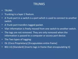
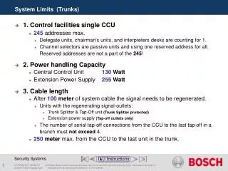
System Limits (Trunks) • 1. Control facilities single CCU • 245 addresses max. • Delegate units, chairman's units, and interpreters desks are counting for 1. • Channel selectors are passive units and using one reserved address for all. Reserved addresses are not a part of the 245! • 2. Power handling Capacity • Central Control Unit 130 Watt • Extension Power Supply 255 Watt • 3. Cable length • After 100 meter of system cable the signal needs to be regenerated. • Units with the regenerating signal-outlets: • Trunk Splitter & Tap-Off unit (Trunk Splitter protected) • Extension power supply (Tap-off outlets only) • The number of serial tap-off connections from the CCU to the last tap-off in a branch must not exceed 4. • 250 meter max. from the CCU to the last unit in the trunk. I&U Instructions DCNNG SA SD Design Calc
Power Consumption in Watt • Discussion Unit with fixed microphone 2.75 W • Discussion Unit 2.75 W • Discussion Unit with Channel selector 2.9 W • Discussion Unit Dual 2.8 W • Discussion Unit Dual with channel selector 3.15 W • Discussion Unit with voting 3.05 W • Discussion Unit with voting and channel selector 3.20 W • Concentus Chairman unit 4.2 W • Concentus basic unit 3.4 W • Concentus with channel selector 3.7 W • Concentus full function 4.2 W • Voting Unit 1.0 W • Dual Delegate Interface 4.5 W Inclusive all connected FM panels. I&U Instructions DCNNG SA SD Design Calc
Power Consumption in Watt • Interpreter’s Desk 3.6 W • Channel selector unit 0.9 W • Data distribution unit 2.0 W • Extension Power Supply 0.8 W • Trunk Splitter 1.3 W • Tap-Off Unit (Trunk Splitter Protected)1.4 W Watt value includes the 2 meter (6.5 ft.) unit-cable. • Audio Expander Analogue 7.6 W • Audio Expander Digital 6.0 W • Cobra net interface 10.5 W • Optical Network splitter 3.9 W • Fiber Interface (POF/GOF or GOF/POF) 4.6 W I&U Instructions DCNNG SA SD Design Calc
Trunk Tap-off 65 W 65 W 85 W 65 W 65 W 85 W 85 W 65 W 65 W 65 W 130 W 255 W 130 W Power handling capacities Central Control Unit Central Control Unit Extension Power Supply DCN-CCUB DCN-CCU DCN-EPS I&U Instructions DCNNG SA SD Design Calc
Max. all trunks: • 36 Interpreter desks • 100 Channel selectors or Central Control Unit 1 n 18 n 50 1 Cable length per outlet to the last unit 100M Max. number of units within 100M from CCU • Max. per trunk: • 18 Interpreter desks • 50 Channel selectors or I&U Instructions DCNNG SA SD Design Calc
Max. all trunks: • 36 Interpreter desks • 140 Channel selectors or Central Control Unit 1 n 18 50 1 TS 51 70 * * Max. Cable length 100m * Tap-off outlets. Max. number of units connected to the CCU • Max. per trunk: • 18 Interpreter desks • 70 Channel selectors or I&U Instructions DCNNG SA SD Design Calc
Max. all trunks: • 69 Interpreter desks • 150 Channel selectors or Trunk Tap-off Extension Power Supply 1 n 23 n 50 1 n 50 1 Cable length per outlet to the last unit 100M Max. number of units within 100M from EPS • Max. per trunk: • 23 Interpreter desks • 50 Channel selectors or I&U Instructions DCNNG SA SD Design Calc
Max. all trunks: • 69 Interpreter desks • 270 Channel selectors or Trunk Tap-off * * * * * Tap-off outlets. Max. number of units connected to the EPS • Max. per trunk: • 23 Interpreter desks • 90 Channel selectors or Extension Power Supply 1 n 23 50 1 51 90 LBB4114 50 1 51 90 LBB4114 Max. Cable length 100m I&U Instructions DCNNG SA SD Design Calc
Extension Power Supply Trunk-in Trunk-out ** * * * Tap-off outlets which regenerating the digital signal. Trunk Outlet & Tap-Off Outlets • For Trunk-cable splitting with regenerating the digital signal. Trunk Splitter & Tap-Off unit (trunk splitter protected) I&U Instructions DCNNG SA SD Design Calc
* * * Tap-off outlets with a limitation of 4,5 Watt. * * Using the Tap-Off unit (Trunk Splitter Protected) LBB4115 LBB4115 I&U Instructions DCNNG SA SD Design Calc
Central Control Unit Tap-off Trunk-line Trunk Splitter Tap-off Trunk-line Loop Through Tap-Off Limitations Extension Power Supply 1st Tap-off 2nd Tap-off 1st Tap-off 3rd Tap-off 2nd Tap-off 4th Tap-off 3rd Tap-off 5th Tap-off 4th Tap-off I&U Instructions DCNNG SA SD Design Calc
Central Control Unit Regenerative Tap-off Trunk Splitter Extension Power Supply Regenerative Tap-off Trunk Splitter Extension Power Supply Maximum Cable Lengths 250M I&U Instructions DCNNG SA SD Design Calc
Central Control Unit 10m (32.8ft.) 20m (65.6ft.) 50m (164ft.) Longest Extension Cable example • The length of cable used in a system has a direct influence on the load of a system. • The second in- line trunk- splitter has two extension cables connected to it, with lengths of 20 m and 50 m. • When determining the cable length of a Trunk-outlet or Tap-off outlet, the longest extension cable only is taken in to account. • Therefore, the total extension cable lengthfrom a single Trunk-outlet of the CCU is calculated as 10+50= 60 m (196.8 ft.) I&U Instructions DCNNG SA SD Design Calc
Central Control Unit 10x 5x 1 2 40m. Max. Cable length 100m 50m. 12x 12x * TS 15m. 12x 12x To EPS See next slide * TS Power calculation Example-1 LBB4114 Example DCNNG SA SD Design Calc
Trunk Tap-off Extension Power Supply 10x 10x 35m. 3 4 5 20m. 20x 20x 20m. 22x 15x * 40m. 20x 10x TS 20m. 15x 24x * Max. Cable length 100m TS Power calculation Example-2 LBB4114 LBB4114 Example DCNNG SA SD Design Calc
Cable correction graph I&U Instructions DCNNG SA SD Design Calc
System Limits (Optical) • 1. Maximum number of nodes is 63 • 2. Maximum number of optical devices is 16 • 3. Optical Plastic Fiber length is maximum 50 Meter • 4. Maximum Optical cable length is depending of the number of nodes in the system I&U Instructions DCNNG SA SD Design Calc
Number of nodes per optical unit • Basic Central Control Unit 0 • Central Control Unit 2 • Audio Expander LBB4402/00 1 • Digital Audio Expander 1 • CobraNet Interface 1 • Optical Network Splitter 1 • Fiber Interface POFGOF & GOFPOF 0 • Integrus Transmitter 4 channels 1 • Integrus Transmitter 8 channels 2 • Integrus Transmitter 16 channels 4 • Integrus Transmitter 32 channels 8 I&U Instructions DCNNG SA SD Design Calc
Fiber interface without address • The fiber interface is used to: • convert from plastic optical fiber (POF) cable to glass optical fiber (GOF) cable and vice versa. • cover distances of more than 50 m in the optical network. LBB4414/10 LBB4414/10 I&U Instructions DCNNG SA SD Design Calc
Nodes Cable lengths graph I&U Instructions DCNNG SA SD Design Calc
Optical connections Central Controle Unit Integrus Transmitter CobraNet Interface Audio Expander I&U Instructions DCNNG SA SD Design Calc
System Design and Calculation End of section SA SD Menu DCNNG SA SD Design Calc