Download
1 / 44
440 likes | 466 Vues
Explore basic encoding techniques like Amplitude-Shift Keying (ASK), Frequency-Shift Keying (FSK), and Phase-Shift Keying (PSK) in digital data transmission. Learn about spread spectrum modulation methods that increase signal bandwidth. Discover the benefits of spread spectrum in combating noise and interference while enabling secure communication.

E N D
Basic Encoding Techniques • Digital data to analog signal • Amplitude-shift keying (ASK) • Amplitude difference of carrier frequency • Frequency-shift keying (FSK) • Frequency difference near carrier frequency • Phase-shift keying (PSK) • Phase of carrier signal shifted
Amplitude-Shift Keying • One binary digit represented by presence of carrier, at constant amplitude • Other binary digit represented by absence of carrier • where the carrier signal is Acos(2πfct)
Amplitude-Shift Keying • Susceptible to sudden gain changes • Inefficient modulation technique • On voice-grade lines, used up to 1200 bps • Used to transmit digital data over optical fiber
Binary Frequency-Shift Keying (BFSK) • Two binary digits represented by two different frequencies near the carrier frequency • where f1 and f2 are offset from carrier frequency fc by equal but opposite amounts
Binary Frequency-Shift Keying (BFSK) • Less susceptible to error than ASK • On voice-grade lines, used up to 1200bps • Used for high-frequency (3 to 30 MHz) radio transmission • Can be used at higher frequencies on LANs that use coaxial cable
Multiple Frequency-Shift Keying (MFSK) • More than two frequencies are used • More bandwidth efficient but more susceptible to error • f i= f c+ (2i – 1 – M)f d • f c= the carrier frequency • f d= the difference frequency • M = number of different signal elements = 2 L • L = number of bits per signal element
Multiple Frequency-Shift Keying (MFSK) * • To match data rate of input bit stream, each output signal element is held for: Ts=LT seconds • where T is the bit period (data rate = 1/T) • So, one signal element encodes L bits • * will not covered in the lecture
Multiple Frequency-Shift Keying (MFSK)* • Total bandwidth required 2Mfd • Minimum frequency separation required 2fd=1/Ts • Therefore, modulator requires a bandwidth of Wd=2L/LT=M/Ts
Phase-Shift Keying (PSK) • Two-level PSK (BPSK) • Uses two phases to represent binary digits
Phase-Shift Keying (PSK) • Differential PSK (DPSK) • Phase shift with reference to previous bit • Binary 0 – signal burst of same phase as previous signal burst • Binary 1 – signal burst of opposite phase to previous signal burst
Phase-Shift Keying (PSK)* • Four-level PSK (QPSK) • Each element represents more than one bit
Phase-Shift Keying (PSK)* • Multilevel PSK • Using multiple phase angles with each angle having more than one amplitude, multiple signals elements can be achieved • D = modulation rate, baud • R = data rate, bps • M = number of different signal elements = 2L • L = number of bits per signal element
Quadrature Amplitude Modulation • QAM is a combination of ASK and PSK • Two different signals sent simultaneously on the same carrier frequency
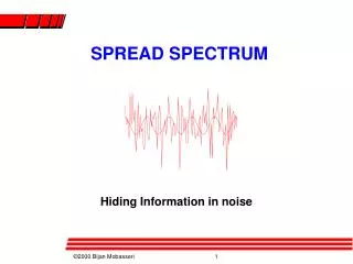
Spread Spectrum • Input data are modulated using sequence of digits • Spreading code or spreading sequence • Generated by pseudonoise, or pseudo-random number generator • Effect of modulation is to increase bandwidth of signal to be transmitted
Why Spread Spectrum • What can be gained from SS? • C = B Log2 (1+ S/N) • Immunity from various kinds of noise and multipath distortion • Can be used for hiding and encrypting signals • Several users can independently use the same higher bandwidth with very little interference
Frequency Hoping Spread Spectrum (FHSS) • Signal is broadcast over seemingly random series of radio frequencies • A number of channels allocated for the FH signal • Signal hops from frequency to frequency at fixed intervals • Transmitter operates in one channel at a time • Bits are transmitted using some encoding scheme • At each successive interval, a new carrier frequency is selected
Frequency Hoping Spread Spectrum • Channel sequence dictated by spreading code • Receiver, hopping between frequencies in synchronization with transmitter, picks up message • Advantages • Eavesdroppers hear only unintelligible blips • Attempts to jam signal on one frequency succeed only at knocking out a few bits
FHSS Using MFSK* • MFSK signal is translated to a new frequency every Tcseconds by modulating the MFSK signal with the FHSS carrier signal • For data rate of R: • duration of a bit: T = 1/R seconds • duration of signal element: Ts= LT seconds • Tc Ts - slow-frequency-hop spread spectrum • Tc < Ts - fast-frequency-hop spread spectrum
FHSS Performance Considerations • Large number of frequencies used • Results in a system that is quite resistant to jamming • Jammer must jam all frequencies • With fixed power, this reduces the jamming power in any one frequency band
Direct Sequence Spread Spectrum (DSSS) • Each bit in original signal is represented by multiple bits in the transmitted signal • Spreading code spreads signal across a wider frequency band • Spread is in direct proportion to number of bits used • One technique combines digital information stream with the spreading code bit stream using exclusive-OR • Used by IEEE 802.11b
DSSS Using BPSK • Multiply BPSK signal, sd(t) = A d(t) cos(2fct) by c(t)[takes values +1, -1] to get s(t) = A d(t)c(t) cos(2fct) • A = amplitude of signal • fc = carrier frequency • d(t) = discrete function [+1, -1] • At receiver, incoming signal multiplied by c(t) • Since, c(t) x c(t) = 1, incoming signal is recovered
Summary of different Spread Spectrum technologies local oscillator (LO), power amplifier (PA)
Code-Division Multiple Access (CDMA) • Basic Principles of CDMA • D = rate of data signal • Break each bit into kchips (k is the key) • Chips are a user-specific fixed pattern • Chip data rate of new channel = kD
CDMA Example • If k=6 and code is a sequence of 1s and -1s • For a ‘1’ bit, A sends code as chip pattern • <c1, c2, c3, c4, c5, c6> • For a ‘0’ bit, A sends complement of code • <-c1, -c2, -c3, -c4, -c5, -c6> • Receiver knows sender’s code and performs electronic decode function • <d1, d2, d3, d4, d5, d6> = received chip pattern • <c1, c2, c3, c4, c5, c6> = sender’s code
CDMA Example • User A code = <1, –1, –1, 1, –1, 1> • To send a 1 bit = <1, –1, –1, 1, –1, 1> • To send a 0 bit = <–1, 1, 1, –1, 1, –1> • User B code = <1, 1, –1, – 1, 1, 1> • To send a 1 bit = <1, 1, –1, –1, 1, 1> • Receiver receiving with A’s code • (A’s code) x (received chip pattern) • User A ‘1’ bit: 6 -> 1 • User A ‘0’ bit: -6 -> 0 • User B ‘1’ bit: 0 -> unwanted signal ignored
Categories of Spreading Sequences • Spreading Sequence Categories • PN sequences • Orthogonal codes • For FHSS systems • PN sequences most common • For DSSS systems not employing CDMA • PN sequences most common • For DSSS CDMA systems • PN sequences • Orthogonal codes
PN Sequences • PN generator produces periodic sequence that appears to be random • PN Sequences • Generated by an algorithm using initial seed • Sequence isn’t statistically random but will pass many test of randomness • Sequences referred to as pseudorandom numbers or pseudonoise sequences • Unless algorithm and seed are known, the sequence is impractical to predict
Important PN Properties • Randomness • Uniform distribution • Balance property • Run property • Independence • Correlation property • Unpredictability
Properties of M-Sequences* • Property 1: • Has 2n-1 ones and 2n-1-1 zeros • Property 2: • For a window of length n slid along output for N (=2n-1) shifts, each n-tuple appears once, except for the all zeros sequence • Property 3: • Sequence contains one run of ones, length n • One run of zeros, length n-1 • One run of ones and one run of zeros, length n-2 • Two runs of ones and two runs of zeros, length n-3 • 2n-3 runs of ones and 2n-3 runs of zeros, length 1
Properties of M-Sequences* • Property 4: • The periodic autocorrelation of a ±1 m-sequence is
Definitions • Correlation • The concept of determining how much similarity one set of data has with another • Range between –1 and 1 • 1 The second sequence matches the first sequence • 0 There is no relation at all between the two sequences • -1 The two sequences are mirror images • Cross correlation • The comparison between two sequences from different sources rather than a shifted copy of a sequence with itself
Advantages of Cross Correlation • The cross correlation between an m-sequence and noise is low • This property is useful to the receiver in filtering out noise • The cross correlation between two different m-sequences is low • This property is useful for CDMA applications • Enables a receiver to discriminate among spread spectrum signals generated by different m-sequences
Gold Sequences* • Gold sequences constructed by the XOR of two m-sequences with the same clocking • Codes have well-defined cross correlation properties • Only simple circuitry needed to generate large number of unique codes • In following example two shift registers generate the two m-sequences and these are then bitwise XORed
Orthogonal Codes • Orthogonal codes • All pairwise cross correlations are zero • Fixed- and variable-length codes used in CDMA systems • For CDMA application, each mobile user uses one sequence in the set as a spreading code • Provides zero cross correlation among all users • Types • Walsh codes • Variable-Length Orthogonal codes
Walsh Codes* • Set of Walsh codes of length n consists of the n rows of an n ´ n Walsh matrix: • W1 = (0) • n = dimension of the matrix • Every row is orthogonal to every other row and to the logical not of every other row • Requires tight synchronization • Cross correlation between different shifts of Walsh sequences is not zero