Download
1 / 38
380 likes | 820 Vues
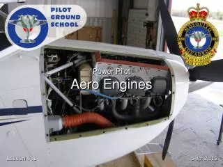
Power Pilot Aero Engines. Reference. From the Ground Up Chapter 3: Aero Engines Pages 47 - 86. Introduction. Aero engines, in particular piston-engines, are complex mechanical machines that create the thrust for an airplane.

E N D
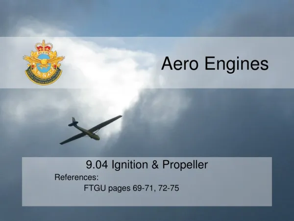
Reference From the Ground Up Chapter 3: Aero Engines Pages 47 - 86
Introduction • Aero engines, in particular piston-engines, are complex mechanical machines that create the thrust for an airplane. • Most new pilots train on piston-engine aircraft, and therefore need to know how the they work.
Outline • Engine Types and Parts • Stroke Cycle • Turbocharging • Cooling and Lubrication • Fuel, Carburetor, and Mixture • Ignition System • Propellers
Horsepower • 1 Horsepower= Work done to raise 33,000 lbs 1 ft in 1 min • Indicated Horsepower = Power developed in an internal combustion engine • Brake Horsepower (BHP) = Power available after friction and other losses
Piston Engines • Radial • Odd number of cylinders (usually 9 max) in a circle • Advantages: Easy maintenance, good air cooling • Disadvantages: Large frontal area (creating drag)
Piston Engines • In-Line • All pistons in a single row • Advantage: Small frontal area • Disadvantages: Bad visibility (unless inverted), long aircraft nose
Piston Engines • Horizontally Opposed • Two banks of cylinders directly opposite each other • 4, 6, or 8 cylinders • Advantages: Flat, small frontal area
Cylinder Parts Spark Plug Camshaft Camshaft Intake Valve Exhaust Valve Combustion Chamber Piston Connecting Rod Crankshaft
Four-Stroke Cycle Induction Stroke Compression Stroke Power Stroke Exhaust Stroke
Four-Stroke Cycle • Induction Stroke • Intake (AKA Inlet) valve open, piston moving down • Negative pressure sucks in fuel/air mixture
Four-Stroke Cycle • Compression Stroke • Both valves closed, piston moving up • Fuel/air mixture is compressed
Four-Stroke Cycle • Power Stroke • Both valves closed, piston moving down • Spark plugs firing ignite fuel/air mixture, combustion forces piston down to create engine energy
Four-Stroke Cycle • Exhaust Stroke • Exhaust valve open, piston moving up • Burned gasses blown out of cylinder
Two-Stroke Cycle • Common on small aircraft, such as ultralights • Combines 4 strokes into 2 with different actions in the Cylinder and crankcase
Turbocharging • Turbocharging • Hot exhaust gasses run compressor • Compressed air provides better fuel/air mixtures at higher altitudes • Supercharging • Same effect as turbocharging, but compressor run off engine crankshaft instead of exhaust gas • Less efficient than turbocharging
Engine Cooling • Most aero engines are air-cooled, with fins on the engine • Shrouds and Baffles force incoming air around engine • Cowl Flaps can open behind engine to allow air to flow around engine quicker, thus increasing cooling
Engine Cooling Fins
Engine Cooling Cowl Flap (full open)
Engine Lubrication • Lubricating oil has four functions: • Cooling • Sealing • Lubrication • Flushing • Oil Viscosity = Resistance to flow (stickiness)
Methods of Lubrication • Force Feed (Dry Sump) • Oil contained in separate tank and pumped throughout engine • Used if engine size is limited (tank can be located in different locations), required for aerobatic or inverted flight • Splash (Wet Sump) • Oil contained at bottom of crankcase, pumped throughout engine, and splashed around by moving parts • Advantages: light weight and relative simplicity (no separate tank and tubing)
Fuel Systems • Fuel Pump • Engine and/or electric pump forces fuel into engine • Required on low-wing aircraft (tanks below engine) • Used on most modern and high-powered aircraft • Gravity Feed • Fuel flows down from tanks to engine • Sometimes used on high-wing, low-power aircraft
Fuel • Octane Rating • Octane = Substance which possesses minimum detonating qualities • Heptane = Substance which possesses maximum detonating qualities • Common Fuels • Grade 80 or 80/87 Red • Grade 100 (high lead) Green • Grade 100 LL (low lead) Blue • Jet Fuel Clear or Straw/Yellow • AVGAS = Aviation Gasoline • MOGAS = Automobile Gasoline
Fuel Problems • Detonation • Fuel burns too quickly and out-of-control • Can cause damage and severe engine malfunction • Caused by using incorrect fuel (too low octane), overheating, or too lean a mixture • Pre-Ignition • Premature ignition due to glowing carbon particles in cylinders • Results in backfiring and severe engine damage • Vapour Lock • Fuel vaporizes in fuel lines, blocking flow of liquid fuel to engine • Caused by high atmospheric temperatures
Carburetor • On older engines, carburetor used to mix fuel and air • Air flowing through venturi creates negative pressure, sucks fuel from fuel nozzle, then mixture flows into cylinders • Throttle controls fuel/air flow with throttle valve • Carburetor can become blocked by ice • Newer engines use Fuel Injection, where fuel is directly injected into cylinder; No hazard of carburetor icing
Carburetor Mixture Valve Venturi Fuel Throttle Valve
Carburetor Icing • Ice can form in carburetor due to low pressure created by venturi • Possible in moist conditions from -5°C to 30°C • Carb Heat control switches incoming air to alternate intake • Intake air is heated by exhaust manifold and is unfiltered air • Hotter air melts ice, but causes slight loss of power (hotter air is less dense)
Carburetor Icing Normal Operation Blocked by Ice
Mixture • Fuel/air mixture adjusted by mixture control • Normal mixture is 1 part fuel to 15 parts air • Rich Mixture (more fuel) = Cooler combustion, more power, used in high power settings • Lean Mixture (less fuel) = Hotter combustion, more economical, used in cruise power settings • Problems: • Too Rich = Wastes fuel, fowls spark plugs, rough engine operation, engine failure • Too Lean = Rough engine operation, cutting-out, detonation, engine failure
EGT • Exhaust Gas Temperature (EGT) Gauge used to determine best fuel/air mixture • Best mixture occurs at hottest EGT reading (Peak EGT)
Ignition System • Magnetos create high tension current from rotating crankshaft to power spark plugs • Usually Dual Ignition (two magnetos); each magneto powers one of two spark plugs in each cylinder • Two spark plugs provide improved combustion in each cylinder • If one magneto fails, other can safely run engine, although with slight loss of power
Propeller • Moves large mass of air backwards at a relatively low speed (as opposed to a jet engine) • Propeller converts engine crankshaft torque (or turning moment) into thrust • Propeller torque is drag (of the propeller blade)
Propeller Pitch • Pitch= Distance in feet a propeller travels forward in one revolution • Pitch determined by the blade's angle of attack • Coarse (high) Pitch = Travels forward more in one revolution; less power, more speed • Fine (low) Pitch = Travels forward less in one revolution; more power, less speed • Propellers can be: • Fixed Pitch = Blade angles cannot be adjusted by pilot; angle is combination of decent take-off performance and cruise performance • Variable Pitch = Blade angles can be adjusted by pilot
Variable Pitch Propellers • Adjustable Pitch = Adjustable only on ground • Controllable Pitch = Adjustable manually by pilot during flight • Constant Speed = Blades adjust automatically to maintain constant RPM as set by pilot; usually operates with oil pressure from engine • Feathering = Blades go to extreme coarse position, to stop propeller wind-milling, usually when engine fails during flight • Prop Reversing = Blades change to negative angle, pushing air forward, used to slow down after landing