Download
1 / 11
110 likes | 219 Vues
Method for Tracking and Mapping a M otion B ased on I mages of the Solar Corona. Petya Pavlova 1 , Elena Duncheva 1 , Kostadinka Koleva 2 1 Technical University Sofia, branch of Plovdiv, Bulgaria 2 Institute of Astronomy, BAS, Bulgaria E-mail: p_pavlova@gbg.bg. Introduction

E N D
Method for Tracking and Mapping a Motion Based on Images of the Solar Corona Petya Pavlova1, Elena Duncheva1, Kostadinka Koleva2 1Technical University Sofia, branch of Plovdiv, Bulgaria 2Institute of Astronomy, BAS, Bulgaria E-mail: p_pavlova@gbg.bg
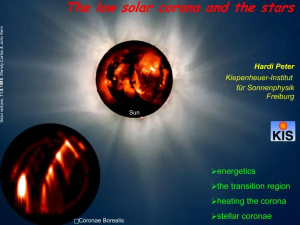
Introduction This work continues the investigations on possibilities of presentation the time development of eruptive solar prominence and related magnetic field described in “Technique for tracking and visualization of motion in sequence of images of the solar corona”. The aim of the work is mapping the direction of movement of different layers of prominence and tracking it’s positions in the sequence of images. The movement produces any displacement that follow some direction. The direction shows possible changes in different layers of prominence and its estimation gives information about the magnetic field behavior. There are two question of interest: -available inhomogeneous is the whole prominence from the point of view of dynamics of eruption and -what are directions of movement available in prominence.
Green 120o Yellow 90o Cyan 180o Red 0o Blue 240o Magenta 300o
A simple technique that uses spatial gradients, gives a possibility to estimate the directions in angular interval. The differences between positions of layerscould be obtained using sequences of computer images of prominence. Pixel based image processing [3] calculates thetime-spatial gradienton the area of four neighbour pixels with same positions into sequenced frames [1]. The ratio between y and x gradient gives degree of deviation - of the lightness of each pixel and is easy imaged by corresponding color hue derived from RGB reproducing signals ( models HSV, HLS, HSI). Giving limits of deviation, all possible directions of movement could be reduced to 8 possible – North, South, West, East, North-West, North-East, South-West, South-East. Using them, a time-dependent map of layers following one direction is possible to be constructed. In addition, rapid changes of directions in sequenced frames that responds to effect of turbulence fix a possible collision.
Fig.1 Compass directions Table 1 describes relations between compass-directions and interval of values in hue used in this image processing. Table 1 Hue limits and compass direction relations
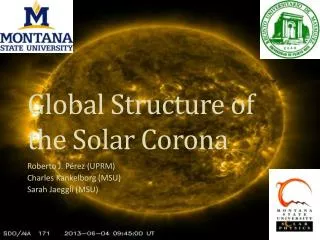
Test experiment The tests in this investigation is carried on sequences of images obtained from 15-cm Lio coronagraph of NAO Rozhen, used for observation of prominence of low solar corona. The images are registered by 8-Mb digital camera CANON 350D and saved in jpg file format. A specially developed software is used for preliminary processing, coinciding the frames in sequences, and obtaining images describing compass directions. The processing includes as follow: - initial analysis and extraction of photo-spherical shining by statistical estimation of the pixels values; - improvement of the images quality applying gauss-filter and sharpen edges; - coinciding the frames into each sequence; • producing gradient images; • extraction of the images in correspondence with the compass directions. • The data about changes of directions are incorporated by values of angle calculated for each pixel. Possible directions are limited between 0 and 360 degrees with 1-degree step of separation.
E NE N NW W SW S SE Results and discussion Fig. 2 Images of layers with pixels with given direction
Fig.3 Compass gradient image An image of colored gradient directions is given in figure 3. Different layers are separated in dependence on defined hue limits.
Three point in the top, middle and bottom position of the prominence (mentioned at the gradient picture) are traced into the period of 25,4 min. Their compass directions are given in Table 2. Time is mentioned as a duration between the first and the subsequent image. The “collision” of opposite directions is marked by red color. Table 2 Directions of movement at the three mentioned points
Summary A special software is developed to separate the part of different motion direction in frames. The separated images form a moving maps of different directions in dependence on the time. The results of the test demonstrate a possibilities to define the time of saving direction of movement in arbitrary points and eliminate flickering. The method also gives a possibility to trace the direction of internal motions in the prominence body .