Download
1 / 18
190 likes | 558 Vues
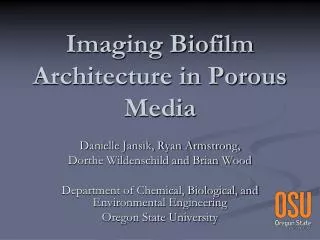
Imaging Biofilm Architecture in Porous Media. Danielle Jansik, Ryan Armstrong, Dorthe Wildenschild and Brian Wood Department of Chemical, Biological, and Environmental Engineering Oregon State University. Biofilms. Consists of Exopolymeric substances (EPS) Polysaccharides DNA Proteins

E N D
Imaging Biofilm Architecture in Porous Media Danielle Jansik, Ryan Armstrong, Dorthe Wildenschild and Brian Wood Department of Chemical, Biological, and Environmental Engineering Oregon State University
Biofilms • Consists of • Exopolymeric substances (EPS) • Polysaccharides • DNA • Proteins • Cells • Numerous microorganisms can form biofilms • Organisms not associated with EPS production can reside in biofilms
Biofilm Basics *Image curtsey the Center for Biofilm Engineering, Montana State University (1995)
*Thormann et al., 2004 CLSM of Shewanella “Polymer production in biofilm has a strong analogy with growth in plants, where competition for light favors vertical growth.” Foster & Xavier, 2006
Research Objectives • To accurately measure 3D architecture of biofilms in porous media • Past quantitative pore scale studies limited to • two-dimensional systems (e.g. Thullner et al., 2002) • Numerous studies of 3D growth on flat substrate (no porous medium) using CLSM • nano-scale observations of the biomass only (minus porous medium) (e.g. Thieme et al., 2003) • 3D studies using CLSM using index-matched system (Leis, 2006) • destructive methods such as thin-sectioning • To provide 3D geometries for validation of existing theory and numerical models
Applications • Water Resource/Environmental Engineering • Packed bed reactors • Bioremediation • Biobarriers • Microbially enhanced oil recovery • CO2 Sequestration • Industrial Applications • Medical Implants • Tissue • Food Processing
Alpkvist (2006) Predicted Architecture of Biofilm • Cluster-and-channel model (mushrooms) • Continuum model (wavy biofilms) • Effect of structural assumption on the resulting expressions for reaction transformation is incompletely understood. Challenges in conceptual model validation: • tremendous spatial and temporal variability of biomass properties as the population grows and changes metabolic characteristic in response to its surrounding environment • difficulty in gathering data at the proper (pore) scale
Methods • Advanced Photon Source at Argonne National Lab • Computed X-ray Microtomography (CMT)
Why tomography? • Three-dimensional information • “Non-destructive” • Fast • High resolution • No need to index-match • Biomass behavior • potential to quantify: • structural arrangement • growth patterns/rates • effect on permeability/hydrodynamics • efficiency of remediation • Specific applications • Describe biofilm structural arrangement (architecture) and relation to and interaction with hydrodynamics • For example image contaminants and biofilm during bioenhanced NAPL clean-up • Where, when (transient behavior), contact area, mass transfer rates, effect on fluid flow…. - flow processes - growth conditions (substrate type, electron donors etc.)
Biofilm Imaging • Most apparent obstacle biomass has very similar x-ray absorption characteristics as water • Silver Coated Hollow Glass Spheres • 25.5 keV • Nominal diameter = 10-20um • Near neutrally buoyant
Experiments Deinococcus Radiodurans • Radioresistant organism • Columns packed with 0.8-1.2 mm glass beads • Flow cell was inoculated with 1.0 mL concentrated solution of D. radiodurans • Static for 24 hrs • Flow rate 0.4 mL/hr • Temperature 30 ° C • Growth time two weeks
Qualitative Results Processed Image of Polystyrene Beads with Biofilms Present – Vertical Slice Contrast Agent: Silver Coated Glass Spheres Processed Image of Polystyrene Beads without biofilms present Contrast Agent: Silver Nanoparticles (500 nm) Processed Image of Glass Beads with Biofilms Present Contrast Agent: Silver Coated Glass Spheres (10-20 um)
Hypothesis • The three dimensional features not attributed to the glass beads or colloidal silver can be tested and confirmed to be biomass. Biofilm
Verification (CMT vs. Microscopy) • Shewanella oneidensis • Forms “true biofilm” • Fast growth rate • Static for 24 hours • Flow (syringe pump) 0.6 ml/hr • Approximately 1 week Two-dimensional micro-model flow cell constructed from PDMS (poly-dimethyl siloxane). Dimensions of the window used for visualization is (6x20x 0.25mm)
Correlating Microscope Images with Tomography Images Microscope 2-D Tomography 3-D
Future Work (this week) • Imaging with the Advance Light Source at Lawrence Berkeley National Laboratory • Correlate microscope images with CMT • To be conducted July 11th • Anticipate data available for validation of theory and numerical models
Acknowledgments: • Fellow Student • Ryan Armstrong • Advisers • Dorthe Wildenschild • Brian Wood • GSECARS • Funding • Subsurface Biosphere IGERT Program • Subsurface Biosphere Initiative • NSF