Download
1 / 20
200 likes | 346 Vues
Robots In Spine Biomechanics. Wafa Tawackoli, Michael A.K. Liebschner Department of Bioengineering Rice University. Motivation. In vitro study of human spine for various complex physiological loading. Prediction of stress fracture risk. Everyday activities

E N D
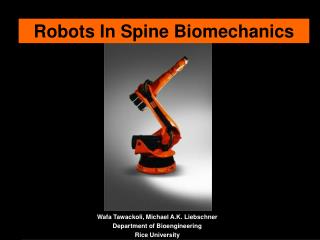
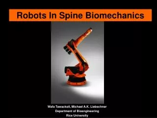
Robots In Spine Biomechanics Wafa Tawackoli, Michael A.K. Liebschner Department of Bioengineering Rice University
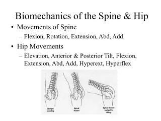
Motivation • In vitro study of human spine for various complex physiological loading. • Prediction of stress fracture risk • Everyday activities • Trauma (i.e. Car accident, Sports) • Occupational ($54 billion/year) • Relatively low impact office duties • High impact manual labor • Osteoporosis (~$13 billion/year) • Approximately 700,000 vertebral fractures occur each year in USA
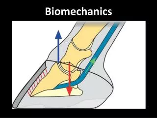
Anatomy Annulus fibrosus Posterior Elements Nucleus pulposus, Facet Joint COR Cortical Shell (rim) Trabecular bone Vertebra IntervertebralDisc Cramer, 1995
To understand the biomechanical behavior of spinal segments under complex physiological loading Primary Goals • 3D motion path • Simulation of in vivo complex loading • Investigate stress fracture risk base on physiological loading
A 3D coordinate system + Z Rotation • Total of 6 load components may be applied • Three forces • Three moments • Each load component may produce 6 displacement components • Three translations • Three rotations • 36 load displacement curves can be generated + X Direction + Z Direction + X Rotation + Y Rotation + Y Direction
Mechanical Properties are difficult to ascertain. Spine movies in a complex 3-Dimensional pattern. However, it is important to apply such complex motion during in vitro studies. Complications
In vivo experiments (including imaging studies, i.e. stereoradiography) (Tibrewan, Pearcy) Mechanical Testing (Panjabi, Hansson, Adams) Computational Modeling (finite element analysis) (Uppala, Williams) Biomechanical Methods
Mechanical Testing Devices Pulley system (Crawford, Panjabi, Patwardhan) Uniaxial system (Adams, Panjabi, Brickmann) (Servo-Hydraulic or Pneumatic) Mechanical Testing Methods Uniaxial compression/tension Shear Bending (Flexion, Extension, Lateral, Torsion) Compressive axial preload (Follower Load) Biomechanical Methods (cont’d)
Biomechanical Methods (cont’d) • Spine Testing Machine: • Pulley system • Linear servo actuator (Parker-EBT 50) • 6 DOF Transducer (ATI-Omega 160) • Bi-axial tilt sensor (range of ~60o) • Optical tracking system • Compressive axial preload capability (up to 2250 N)
Top View Side View Cable guide U-Shape Bracket Biomechanical Methods (cont’d) Flexion Force Extension Force Sagittal View ATI-160 Dead Weights
Measurement of spinal rigidity in single plane is very complex Unconstrained Motion- 6 Degrees of Freedom (DOF) 2 DOF applied force + moment Lack of knowledge of disc degeneration (tears or lesions) Limitations
Measurement of spinal rigidity under complex loading (Fatigue, Creep, Stress Relaxation) Decrease DOF of unconstrained motion Increase DOF of applied forces and moments Apply helical axis of motion (path of minimum resistance) Load and displacement boundary conditions. Our Approach
Wrist Arm Link arm Rotating column Base frame Concept of KUKA Robotic Arm • 6 Degree of Freedom • PC computer • Windows based program (GUI software) • Manual and automatic control • Simple modular system
Coordinate Systems • Coordinate systems (can be defined by the operator): • Sensor & Tool coordinate systems • Base coordinate system • Virtual coordinate system
Sensing and Control Process (1) Displacement EZ NZ Load Hybrid Control = { load control & displacement control }
Sensing and Control Process (2) Forces and torques measured by the ATI transducer can be re-calculated to a virtual coordinate system in order to sense the real effecting forces and torques between spinal segment and the transducer. The optical tracking system allows for comparison in movement between each vertebra.
Motion Envelope Ω Reference (Home) Position φ Foundation Points (Manually determined) Top View of Motion Envelope Boundary condition (i.e. Bending moment of 5 N.m.)
Human spine is a complex system therefore complex motion behavior is expected Hybrid control for biomechanical testing is recommended 6DOF robotic testing system can be applied to the delineation of in vitro spine kinetics Conclusion
Computational and Experimental Biomechanics Lab KUKA USA Robotics KUKA Development Labs ATI Industrial Automation Joe Gesenhues(Ryon Engineering Lab, Rice University) Acknowledgment
Thank You Robots in Biomechanics Research