Download
1 / 27
270 likes | 662 Vues
Susana Izquierdo Bermudez. 29-04-2014. 11T Quench Heater Design. OUTLINE. Quench Heater Design Guidelines Modelling Quench Heater Delays Definition of main Quench Heater Parameters Insulation from Heater to Coil Quench Heater Geometry Quench Heater Circuit

E N D
Susana Izquierdo Bermudez. 29-04-2014 11T Quench Heater Design
OUTLINE • Quench Heater Design Guidelines • Modelling Quench Heater Delays • Definition of main Quench Heater Parameters • Insulation from Heater to Coil • Quench Heater Geometry • Quench Heater Circuit • Trace manufacturing and characterization • Conclusions and final remarks
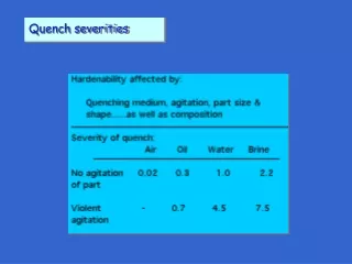
1. QH Design Guidelines • Design should be suitable for a 5.5 m length magnet • The distance between heating stations should be such that the heat has to propagate between stations in less than 5 ms. • For longitudinal propagation ≈ 10 m/s, distance ≈ 100 mm • Kapton insulation thickness from heater to coil should be minimized, but guarantee a good electrical insulation from heater to coil. • 50 µm seems to be minimum reliable Kapton thickness • Heat power density in the heating station should be as high as possible, but the temperature in the heater under adiabatic conditions should not increase above 350K. • Experimental data from LARP magnets and 11T FNAL show that PO ≈ 50-80 W/cm2heater delay starts saturating, but first short models PO up to 150 W/cm2to find the optimal power density. • Heat as many turns as possible in the azimuthal direction. • Power density in the low field region should be higher than in the high field region to quench the magnet in a more uniform way. • No sharp edges, keeping the geometry of the heaters as simple and robust as possible. • If possible, use standard LHC QH power supply. • Total capacitance 7.05 mF , maximum voltage ± 500V. • Maximum current for continuous operation = 135 A • Peak current at 25 ˚C for 10 ms =1700 A (it will probably destroy the PCB of the power supply) • Can be safely operated up to 300 A • At least two independent circuits per aperture (for redundancy)
2. Modelling Quench Heater Delays ROXIE quench heater model First Order Thermal Coupling as implemented in ROXIE heater Heat capacity includes conductor + insulation Thermal conductance and heat fluxes: Conductor without insulation. Uniform temperature in the conductor and linear temperature distribution in between them Extension for QH modelling Tuning factor (k) on GijT,heater2coil/bath to fit experimental and computed heater delays Model validation Experimental data courtesy of Guram Chlachidze k=0.42 MBSHP02: Po LF = 65 W/cm2Po HF=39 W/cm2 =31 ms Insulation heater2coil = 114 µm kapton + 125 µm G10 Insulation heater2bath = 508 µm kapton
3.1 Insulation from heater to coil • Impact of insulation thickness on heater delay • Po =50 W/cm2 2t=15 ms and I/Iss=80 % • Assumptions • Quench heaters are a continuous strip • (no heating stations) • Identical cable insulation scheme (CERN 11T insulation combines S-2 glass and Mica) FNAL 11T coils QH glued after impregnation Measured QH delay tQH ≈ 25 ms LARP approach Trace impregnated with the coil Expected QH delay tQH ≈ 16 ms CERN 11T coils Trace glued after impregnation Expected QH delay tQH ≈ 18 ms 0.025 mm glue+ 0.050mm kapton (trace) QUENCH HEATERS 0.2 mm S2 glass 0.5 mm kapton (ground insulation) 0.125 mm S2 glass 0.025 mm glue + 0.114mm kapton QUENCH HEATERS 0.5 mm kapton (ground insulation) 0.2 mm S2 glass 0.025+ mm glue + 0.050 mm kapton QUENCH HEATERS 0.5 mm kapton (ground insulation)
3.2 Quench heater geometry (1) • Design objective: • Heat as many turns as possible in the same longitudinal section. QH case 1 Pole turn (56) QH case 2 QH case 3 52 54 53 56 55 Q Q Q Simulated turn to turn propagation time: 3 ms in the inner layer pole turn, 22 ms in the outer layer mid-plane Pole turn • Design Objective: • Design suitable for a 5.5 m length magnet • Design Objective: • Distance between heating stations ≈ 100 mm • Design Objective: • Maximum voltage ± 450V Copper plating is a must to reduce the overall strip resistance
3.2 Quench heater geometry (2) Lperiod OPTION 1 Lperiod • For the same power density and voltage drop1: • Less current • Less conductor can be covered longitudinally • Stations are further • Reliability of copper cladding technology? Lcov Lno-cov Lcov Lno-cov 1: More details in “Additional Slides” OPTION 2 • For the same power density and voltage drop: • More current • More conductor can be covered longitudinally • Stations can be closer • All turns (azimuthally) are heated in the same longitudinal section • Issues of current re-distribution? (talk from Juho) • Reliability of copper cladding technology? Baseline solution for 11T: OPTION 2
3.2 Quench heater geometry (3) width Coverage Distance between stations • Width -> Cover as many turns as possible • LF: 19 mm • HF: 24 mm • Power density • LF ≈ 75 W/cm2 • HF≈ 55 W/cm2 Heater width: 19 mm LF, 24 mm HF ρss=7.3·10-7Ωm, RRR=1.34 Operation area Even if the operational current is expected to be in the range 100-120 A, it would be good to have the possibility to go up to 150 A – 200 A during short model tests to check the saturation of the system in terms of heater delays. • Distance between heater stations -> quench propagation in between stations ≈ 5 ms • LF: 90 mm • HF: 130 mm • Coverage: maximum coverage keeping the resistance within the allowable limits for a 5.5m magnet (depends on the number of power supplies/heater circuits)
3.2 Quench heater geometry (4) 3D simulation with heater stations 19/24 50 90/130 Full coverage vs heating stations: 1 MIITs difference Time budget 7 ms higher in case of full coverage • Remarks:ROXIE thermal network has limitations that we try to overcome via fitting factors • More detailed quench heaters model show better agreement with experimental results without any free parameters [Tiina Salmi] • Inter-layer quench propagation computed in ROXIE is a factor 2.5 slower than experimental results • Adaptive mesh tracking is a must for efficient quench simulation [Luca Bottura, MT23]. ROXIE computed longitudinal propagation when using a coarse mesh is slower than expected (and computed when using a very fine mesh)
3.3 Quench heater circuit Design Objective: Stay within LHC standard quench heater supply limits (V = 450 V, C=7.05 mF, Ip≈ 85 A but it can safely operate up to 300 A) Baseline solution: Heater circuit Heater strip 19/24 50 90/130 For a 5.5 m magnet: Remark: each heater circuit can be divided in two if V=450 is preferred than V = 450 V + - + - + - + -
4. Trace manufacturing and characterization • Resistance measurements at RT and 77 K • Stainless steel stations: Measured resistance close to expected values • 3% difference at RT • 8 % difference at 77K • Copper regions: Measured resistance higher • than expected value • 20% difference at RT • 25 % difference at 77K • High current test • No degradation was observed in the bonding • Temperature cycling at 77 K • No degradation Kapton (25 µm) Glue (50 µm) Copper (5 µm) Stainless Steel (25 µm) Glue (<25 µm) Kapton (50 µm) Trace stack for 11T ρss=1.8·10-8Ωm, RRRSS=30 ρss=7.3·10-7Ωm, RRRSS=1.34
7. Conclusions and final remarks • Main differences in between QXF and CERN 11T: • CERN11T uses mica-glass insulation (lower thermal conductivity than G10). • Trace is glued in the coil after impregnation additional layer of 0.2 mm of S2 glass between heaters and coil We should be careful when drawing conclusions from 11T to QXF • Redundancy with only outer layer heaters seems to be more than challenging • Lower margin in the inner layer heaters in the IL will provoke faster quench and more uniform heat propagation within the coil • Could AC losses trigger a quench? how would it impact the rest of the RB circuit?
References • Quench heater experiments on the LHC main superconducting magnets. F. Rodriguez-Mateos, P. Pugnat,S. Sanfilippo, R. Schmidt, A. Siemko, F. Sonnemann • LQ Protection Heater Test at Liquid Nitrogen Temperature. G. Chlachidze, G. Ambrosio, H. Felice1, F. Lewis, F.Nobrega, D. Orris. TD-09-007 • Experimental Results and Analysis from the 11T Nb3Sn DS Dipole. G. Chlachidze, I. Novitski, A.V. Zlobin (Fermilab) B. Auchmann, M. Karppinen (CERN) • EDMS1257407. 11-T protection studies at CERN. B. Auchmann • Challenges in the Thermal Modeling of Quenches with ROXIE. Nikolai Schwerg, Bernhard Auchmann, and Stephan Russenschuck • Quench Simulation in an Integrated Design Environment for Superconducting Magnets. Nikolai Schwerg, Bernhard Auchmann, and Stephan Russenschuck • Numerical Calculation of Transient Field Effects in Quenching Superconducting Magnets. PhD Thesis. Juljan Nikolai Schwerg • Thermal Conductivity of Mica/glass Insulation for Impregnated Nb3Sn Windings in Accelerator Magnets*. Andries den Ouden and Herman H.J. ten Kate • Electrodynamics of superconducting cables in accelerator magnets, Arjan Peter Verweij • Rossi, L. et al. "MATPRO: a computer library of material property at cryogenic temperature." Tech. Report, INFN, 2006. • http://te-epc-lpc.web.cern.ch/te-epc-lpc/converters/qhps/general.stm
Minimize heaters delay: heater design optimization For long magnets, the total heater resistance becomes too high Heating stations 2 possible options: Heating stations LARP LQ example: wide section = 23 mm, narrow section 9 mm, distance between stations 100mm LHC copper plated solution MB example: 15 mm width, 400 mm plated, 120 mm un-plated Qualitative tests at CERN to understand how smooth the transition between narrow and wide section should be in order to avoid high spot temperatures. More development required to find a solution which combines smooth transition, enough coverage and distance in between heater stations small enough to allow fast quench propagation in the longitudinal direction BASELINE SOLUTION FOR THE FIRST MODEL = COPPER PLATED SOLUTION Thanks to Vladimir Datskov & Glyn Kirby
Minimize heaters delay: inter-layer heaters CASE 2: Outer Layer + Inter Layer Heaters • Heater parameters: • Insulation heater2coil = 114 µm kapton + 125 µm G10 + conductor insulation • Insulation heater2bath = 508 µm kapton • Po = 70 W/cm2 , =74 ms, ΔtQHdelay=5 ms • Non-redundant configuration CASE 1: Only Outer Layer Heaters Δ OL HF QHdelay= - 31 % ΔIL QHdelay= - 88 % ΔTmax= - 27 % Some technical development required before inter-layer heaters become a feasible option • Remarks: • Thermal contact resistances (e.g. between insulation layers) not included, the same scaling factor as the one used to fit the FNAL test data is kept for this simulation. • The insulation is a combination of glass fiber and Mica. At the moment in the model we use G10.
Minimize heaters delay: reduce kapton thickness CASE 1: Insulation heater2coil = 114 µm kapton + 125 µm G10 + conductor insulation Insulation heater2bath = 508 µm kapton CASE 2: Insulation heater2coil = 50 µm kapton + 125 µm G10 + conductor insulation Insulation heater2bath = 508 µm kapton Po = 64 W/cm2 (LF), 39 W/cm2 (HF) =31 ms, ΔtQHdelay=5ms Non-redundant configuration Quench validation: 100mV, 10ms Δ OL HF QHdelay= - 33 % ΔTmax= - 13 %
Protection System LHC Magnets The Protection System for the Superconducting Elements of the Large Hadron Collider at CERN K. Dahlerup-Petersen1, R. Denz1, J.L. Gomez-Costa1, D. Hagedorn1, P. Proudlock1, F. Rodriguez-Mateos1, R. Schmidt1 and F. Sonnemann2
STANDARD LHC HEATER POWER SUPPLIES QUENCH HEATER EXPERIMENTS ON THE LHC MAIN SUPERCONDUCTING MAGNETS F. Rodriguez-Mateos, P. Pugnat,S. Sanfilippo, R. Schmidt, A. Siemko, F. Sonnemann Supply based on the thyristor-triggered discharge of aluminium electrolytic capacitors. Each power supply contains a bank with 6 capacitors (4.7 mF/500V) where two sets of 3 parallel capacitors are connected in series total capacitance 7.05 mF Nominal operating voltage 450 V (90 % of the maximum voltage) OPERATION: Peak current about 85 A, giving a maximum stored energy of 2.86 kJ Actual limitations in terms of current Power supply equipped with two SKT80/18E type thyristors rated for 80 A at 85 ˚C. Maximum current for continuous operation = 135 A Peak current at 25 ˚C for 10 ms=1700 A (it will probably destroy the PCB of the power supply) Can be safely operated up to 300 A (resistive load in LHC from 12Ω in most of the circuits to 3.1 Ω in some systems such as D1 protection )
Impact of insulation material/thickness Kapton G10 Thermal conductivity Heat capacity https://espace.cern.ch/roxie/Documentation/Materials.pdf
ROXIE Thermal Network Lumped thermal network model in comparison to the coil/conductor geometry Tbath GijT,heater2coil GijT,heater2bath GijT,heater2coil
Tmaxvs MIITs Experimental Results and Analysis from the 11T Nb3Sn DS Dipole G. Chlachidze, I. Novitski, A.V. Zlobin (Fermilab) B. Auchmann, M. Karppinen (CERN) “To keep the cable temperature during a quench below 400 K, the quench integral has to be less than 19-21 MIITs“
Quench heater geometry OPTION 1 Lperiod Lcov Lno-cov wB wA wA=w wB=1/3w OPTION 2 Lperiod Lcov Lno-cov w For the same power density and voltage drop: =
Trace manufacturing and characterization • Before trace installation • Resistance measurements at RT • High voltage test to ground under 20-30 MPa pressure (2kV). • After trace installation, every step of the manufacturing process Expected value: R1=R2=1.65 Ω Measured value ≈ 1.7 Ω • Resistance • QH to ground and QH to coil (1 kV) • Discharge test (pulse). Low thermal load to the heaters (under adiabatic conditions and assuming constant material properties, peak current defined to limit the temperature increase to 50 K) (only in the manufacturing steps after collaring)