Download
1 / 25
250 likes | 412 Vues
QXF heater design. M. Marchevsky , D.W . Cheng (LBNL) E. Todesco (CERN) T. Salmi (Tampere UT) G. Chalchidze , G. Ambrosio (FNAL). O utline. H eater design challenges and goals “Stainle ss only” heater design for SQXF / LQXF Copper plated design options for the OL

E N D
QXF heater design M. Marchevsky, D.W. Cheng (LBNL) E. Todesco (CERN) T. Salmi (Tampere UT) G. Chalchidze, G. Ambrosio (FNAL)
Outline • Heater design challenges and goals • “Stainless only” heater design for SQXF / LQXF • Copper plated design options for the OL • Copper plated design options for the IL • Summary of the designs and future work
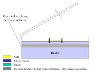
Basic concepts • Active protection: upon detecting the quench, the goal is to create the largest normal zone in the shortest possible time Uniform strip (t1 , t2=0) t1– thermal diffusion time (heater delay) Strip with heating stations (t1 , t2) t2 – quench propagation time Heating stations t1 t1 t2 t2 t2 Quench propagation • Large spacing L between the heating stations -> higher surface power density -> shorter t1, but longer t2of the quench propagation between the heated areas • Small spacing L between the heating stations > smallerheater power -> longer t1, but shorter t2of the quench propagation between the heated areas
Heater design steps for QXF • Establish a set of operational and dimensional design criteria • We agreed that SQXF and long QXF should share same design criteria to ensure the above statement is valid and the SQXF heater performance is relevant to the long QXF. • Determine heater time delays through experiments and simulations • Design heater patterns to satisfy the minimal protection requirements • Further optimize heater efficiency and layouts based on recent performance tests (HQ, LHQ) and simulations Our goal is to learn the most about long QXF protection from the SQXF heater performance. We will use SQXF to validate and optimize the final QXF design.
SQXF vs QXF Patterns were developed individually for the short (1 m) and long (~6.7 m) QXF model, sharing the same: • Heater material (SS304) and Kaptontrace thickness (50 micron) • end-to-end heater configuration and layout • heating station geometry • concept behind periodicity of the heating stations - it is derived from the twist pitch of the cable • power per heating station (in SQXF, we will set it to match the long QXF equivalent by choosing an appropriate HFU voltage) IL: 2 heaters OL: 4 heaters
Input: quench delay vs heater peak power density Simulations Experiments TQ T. Salmi WAMSDO 2013 Power density > 50 W/cm2 is desirable LQ OL heaters fired Delay increases by 60% when Kapton layer thickness is increased from 25 μmto 50 μm
Heater delay simulations vs HS coverage and period Coverage = length of heating station segment along the cable WAMSDO 2013, T. Salmi Period = Distance between heating stations B = Bpeak By going from ~10 mm wide heating station to a continuous strip, one can gain ~1 msof the heater delay time (equivalent to ~0.25 MIITS at 16 kA). HS length > 20 mm is desirable.
Matching the cable twist pitch Heating station width, w Cable twist pitch, p Distance between heating stations, l • If p = 2nw and l = (2n+(-)1) w, then the supercurrent in all strands of the cable segment of length L= n l can be “interrupted” simultaneously by the normal zones created with n heating stations. • This approach can potentially improve heater efficiency, as all cable strands will get resistive and start dissipating heat at once
SQXF/LQXF agreed heater design parameters Peak power density:50-150 W/cm2 HFU voltage: up to 450 V HFU current: up to 220 A HFU capacitance: 4.8-19.2 mF Distance between heating stations:up to 120 mm (Could be related to the transposition pitch of 109 mm) Trace parameters: Kapton Insulation thickness: 50 µm Stainless Steel thickness: 25 µm Copper thickness: 10 µm Glue thickness: up to 25 µm Coil surface coverage by trace:< 50 % IL Distance from heater to coilor voltage taps:4 mm or more
SQXF outer layer, “SS only” design HOPMT =HIPMT = 23.7 mm 18 segments b = 38 mm (Per 1.075 m) Lseg= 60.7 mm a = 10.48 mm (=> 12.11 mm along the cable) r1 = 3 mm ; L = 15 mm; a = 60 deg; m = 3 mm Rheater= 1.48 W At 100 V => 67 A and 82 W/cm2 per straight portion of the heating station r=5*10-7W m, d = 25 mm ½ twist pitch base p = (2n-1) w l = nw To satisfy the 4 mm gap between heaters and coil boundaries / Vtaps requirement, the choice was made for the ~24 mm wide heater pattern, allowing placing two heater strips of identical geometry per each coil side. p = 109 mm 5 segments (303.5 mm length) will provide simultaneous quenching of all strands.
Long QXF “SS-only” option for the OL Long QXF (Per 6.70 m) p = (n div 2-1)w l=nw 29 segments Lseg= 230 mm At 450 V => 69 A and 87 W/cm2 per straight portion of the heating station 2x twist pitch base HOPMT =HIPMT = 23.7 mm Rheater= 6.49 W One will need to increase the period of the heater pattern to 230 mm (2x twist pitch +1 station) in order to be within the required range of power densities. This in turn will add ~10 ms to the heater total delay due to increased quench propagation time between the HS.
SQXF inner layer, “SS only” design LIMMT = 30.75 mm and LIPMT = 9.19 mm Entire inner layer: 45.51 mm If we were to place two separate heaters for the inner layer like we did for the outer layer, the only feasible heater structure for the pole multi-turn LIPMTwould be a straight strip. Even then, at 6.7 m length and 9.2 mm width its resistance will be ~14.6 W – too high!Therefore, we combined mid-plane and pole block heaters in one that spans across the spacer and portions of both (pole and mid-plane) multi-turns. It occupies ~65% of the trace width along the winding. Hseg= 30.75 mm 16 segments SQXF (1.0 m) Lseg= 61.3 mm • b = 33 mm Rheater= 1.42 W 5 segments (303.5 mm length) will provide simultaneous quenching of all strands. a = 10.48 mm (=> 12.11 mm along the cable); r1 = 3 mm; L = 15 mm; a = 60 deg; m = 3 mm wedge
SQXF final trace for Coil 1 D. Cheng • The masks were produced and one trace was manufactured. Hipot test of the trace is pending.
Can the SQXF design be directly used for LQXF? YES – by applying copper plating 6.7 m The SQXF original design extended to 6.7 m length yield ~110 heating stations and the net resistance of 9.1 Ohm => 49 A (at 450 V) and 45 W/cm2 per heating station – too low. But we can scale up the length of the original heating station design, by plating copper only on the wide portions of the heater: If we plate the “pads” with 10 micron of Cu, the net resistance will drop to 5.6 W => 80 A (at 450 V) and 116 W/cm2 Assuming rCu= 3.6 10-9W m (at 100 K) This is still an option for the long QXF
Copper plating: a game changer? • One can possibly form heating stations in the straightSS strip by selectively applying copper plating • Advantage: easier fabrication, larger heating stations (so potentially smaller delay), more power delivered overall • Disadvantage: higher heater currents, continuous coverage along the turns may favor bubbles (IL only) • Open questions: electrical integrity, current uniformity • Furthermore, many “hybrid” solutions are possible, that can be optimized for the winding layout, field distribution, etc…
OL “Cu-plated” design, option 1 • 2 separatelypoweredstrips / coil side • Stripwidth 20 mm • HS length and periodoptimizedusing CoHDA • 7 T and 5 T @17500 A • NZPV = 5 m/s T. Salmi
Optimization results for the OL • Optimization is done by minimizing the sum of (PH delay + quench propagation time between the HS). 7 T – 20 mm widestrip 5 T – 20 mm widestrip Negligibledifference.. Adjustment of the period to match the cable twist pitch is to be done here… T. Salmi
“Cu-plated” OL design, option 2 E. Todesco • Power up to 200 W/cm2 (at 200 A) SS Cu Cu 120 mm 40 mm
“Cu-plated” IL design, option 1: “snake” pattern • Strip full span = 22 mm (leaving > 50 % free at thecoil midplane), covering • 4 turns on pole block (~7.2 mm) • 5 turns on midplane block (~9.2 mm) • Heating station (HS) width = 10 mm • HS length and period optimization (CoHDA) • B = 9 T, NZPV = 10 m/s bridge across the wedge T. Salmi
Dimensional optimization • Optimization is done by minimizing the sum of (PH delay + quench propagation time between the HS). • Result (adjusted for the pitch length of 109 mm): • HS length = 18.32 mm • period = 91 mm • τRC = 36 ms, R = 5.6 Ω, I = 80 A • P(0) = 130 W/cm2 • PH delay = 13 ms, • propagation between HS = 4 ms • The CAD version of the IL SQXF trace is now under development T. Salmi
“Cu-plated” IL design, option 2 E. Todesco • Reduced width of the copper-plated bridges (more space available for holes) • Increased width of the heating station • Cooper-plated terminals of the heating stations to improve current flow uniformity
Comparative parameter table for the IL designs ”Cu” - IL Option 1 (Tiina) ”Cu” - IL Option 2 (Ezio)
Comparison of the delays (simulation) Simulation for 100 W/cm2, τ = 47 ms Heaterdelaysat nominalcurrent IL – Option 1 • Firstdelay = 9 ms • Average* delay = 12 ms IL – Option 2 • Firstdelay = 9 ms • Average* delay = 11 ms • Firstdelay = 12 ms • Average* delay = • 20 ms (LF block) • 14 ms (HF block) OL *Using medium field (no quenchpropag. incl.) T. Salmi
Current status summary and planning Trace CAD • Coil 1: LARP • IL :“SS only” • OL: “SS only • Coil 1: CERN • IL :“SS only” • OL: “SS only” • Coils 2-3: LARP • IL: “Cu plating” option 1 • OL: “SS only” • Coils 2-3:CERN: • IL: “Cu plating” IL, option 2 • OL: “Cu plating” OL option 1 or 2 v v v v v x v x In progress x v x x x x x
Remaining questions • Low field / low current performance • It appears that much longer heating station (or more power) is needed to initiate quench at < 5 kA. Additional optimization and/or alternative solutions may be needed for the OL mid-plane block heater strip. • Formation of “bubbles” under the IL heater trace • Bubble formation was observed routinely in LQ coils under the “wide” portions of the inner layer SS heater element. It is unclear if increasing the heating station length along the cable will induce same type of problem • Is “more power and larger area” always a good approach for improving protection performance? Or can one do a better job (or same job with less current / stress/ heat gradients) using targeted heat deposition through a better layout optimization? Side-by-side testing is needed to answer thisquestion.