Download
1 / 33
330 likes | 557 Vues
Susana Izquierdo Bermudez. Magnet protection studies and heater design. OUTLINE. Margin and MIITs overview Quench study based on FNAL 11T tests results Longitudinal quench propagation Heaters delay Quench Integral (QI) Time budget Minimize heaters delay Inter-layer heaters

E N D
Susana Izquierdo Bermudez Magnet protection studies and heater design
OUTLINE • Margin and MIITs overview • Quench study based on FNAL 11T tests results • Longitudinal quench propagation • Heaters delay • Quench Integral (QI) • Time budget • Minimize heaters delay • Inter-layer heaters • Reduce kapton thickness from heater to coil • Quench heater design optimization • Quench performance under accelerator conditions • Additional remarks • Baseline design • Conclusions/Future actions
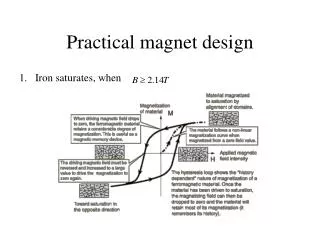
1. Margin and MIITs overview T(MIITs) 11T cable Temperature Margin 14.5 K 5 K 11 T, 11.22 T central field
2.Quench study based on FNAL 11T tests: longitudinal quench propagation Longitudinal quench propagation 2D+1 thermal network Study the propagation of an initial resistive zone of 3 cm length in different turns. I = 11850 A, Tbath=1.9K Element size in the longitudinal direction = 1 mm Adaptive time stepping (min = 10-7s, max = 10-5s] Pole turn IL (high field) v ≈ 30 m/s Mid-plane turn OL (low field) v ≈ 6.5 m/s Block 6: 13.4 m/s Block 5: 7.2 m/s The longitudinal quench propagation velocity in MBHSP01 was measured in one of the quenches in the inner-layer pole turn at 4.5 K using the time-of-flight method as ~27 m/s at 73% of SSL at 4.5 K Experimental data courtesy of Guram Chlachidze
2.Quench study based on FNAL 11T tests: Quench Heaters Delay HFU voltage of 400 V ~ 65 W/cm2 peak power density ROXIE quench heater model Experimental data courtesy of Guram Chlachidze heater k=0.42 Tuning factor (k) on GijT,heater2coil/bath to fit experimental and computed heater delays MBSHP02: Po LF = 65 W/cm2Po HF=39 W/cm2 =31 ms Insulation heater2coil = 114 µm kapton + 125 µm G10 Insulation heater2bath = 508 µm kapton
2.Quench study based on FNAL 11T tests: QI study • Manual trips with the two operating protection heaters • Dump delay 1000 ms Self-dump Experimental data courtesy of Guram Chlachidze Max. Temperature [K] • I0 = 11850 A, Tbath = 1.9 K Heaters fired @ t=0 OL quenched @ measured delay
2.Quench study based on FNAL 11T tests: QI study • Manual trips with the two operating protection heaters • Dump delay 1000 ms Self-dump QI after heaters effective 0.84 MIITs difference Additional time budget: 6 ms Remark: MATPRO database material properties. MIITs 6 % lower for CUDI/Cryocomp database (mainly due to Copper Thermal Conductivity) https://espace.cern.ch/roxie/Documentation/Materials.pdf Experimental data courtesy of Guram Chlachidze
2.Quench study based on FNAL 11T tests: Time budget Redundant (half of the quench heaters fired) Non-redundant (all quench heaters fired) QIdecay = 10.8 MA2s QIdecay = 11.6 MA2s (experimental) (experimental) QImax = 18 MA2s I0= 11850 A • Detection time: • Time to get over the threshold : 3-6 ms • Validation time : 10 ms • Heating firing delay : 5 ms* • Heater delay (experimental): 27 ms Time needed to quench: 45-48 ms We are tight! We need to minimize heaters delay • *actual value in RB circuits 30 ms
3. Minimize heaters delay: inter-layer heaters CASE 2: Outer Layer + Inter Layer Heaters • Heater parameters: • Insulation heater2coil = 114 µm kapton + 125 µm G10 + conductor insulation • Insulation heater2bath = 508 µm kapton • Po = 70 W/cm2 , =74 ms, ΔtQHdelay=5 ms • Non-redundant configuration CASE 1: Only Outer Layer Heaters Δ OL HF QHdelay= - 31 % ΔIL Qhdelay= - 88 % ΔTmax= - 27 % Some technical development required before inter-layer heaters become a feasible option • Remarks: • Thermal contact resistances (e.g. between insulation layers) not included, the same scaling factor as the one used to fit the FNAL test data is kept for this simulation. • The insulation is a combination of glass fiber and Mica. At the moment in the model we use G10.
3. Minimize heaters delay: reduce kapton thickness CASE 1: Insulation heater2coil = 114 µm kapton + 125 µm G10 + conductor insulation Insulation heater2bath = 508 µm kapton CASE 2: Insulation heater2coil = 50 µm kapton + 125 µm G10 + conductor insulation Insulation heater2bath = 508 µm kapton Po = 64 W/cm2 (LF), 39 W/cm2 (HF) =31 ms, ΔtQHdelay=5ms Non-redundant configuration Quench validation: 100mV, 10ms Δ OL HF QHdelay= - 33 % ΔTmax= - 13 %
3. Minimize heaters delay: heater design optimization Circuit 2 Circuit 1 DESIGN GUIDELINES Heaters should cover as many turns as possible Design should be suitable for a 5.5 m length magnet heating stations Aiming to heater delays < 20 ms Two independent circuits (for redundancy). Higher power density in the LF region
3. Minimize heaters delay: heater design optimization For long magnets, the total heater resistance becomes too high Heating stations 2 possible options: Heating stations LARP LQ example: wide section = 23 mm, narrow section 9 mm, distance between stations 100mm LHC copper plated solution MB example: 15 mm width, 400 mm plated, 120 mm un-plated Qualitative tests at CERN to understand how smooth the transition between narrow and wide section should be in order to avoid high spot temperatures. More development required to find a solution which combines smooth transition, enough coverage and distance in between heater stations small enough to allow fast quench propagation in the longitudinal direction BASELINE SOLUTION FOR THE FIRST MODEL = COPPER PLATED SOLUTION Thanks to Vladimir Datskov & Glyn Kirby
3. Minimize heaters delay: heater design optimization width Coverage Distance between stations Operation area • Width -> Cover as many turns as possible • LF: 20 mm • HF: 24 mm • Power density • LF ≈ 75 W/cm2 • HF:≈ 55 W/cm2 Heater width: 20 mm LF, 24 mm HF ρss=7.8·10-7Ωm, RRR=1.34 Even if the operational current is expected to be in the range 100-120 A, it would be good to have the possibility to go up to 150 A during short model tests to check the saturation of the system in terms of heater delays. • Distance between heater stations -> quench propagation in between stations ≈ 5 ms • LF: 90 mm • HF: 130 mm • Coverage: maximum coverage keeping the resistance within the allowable limits for a 5.5m magnet (depends on the number of power supplies/heater circuits)
3. Minimize heaters delay: heater design optimization OBJECTIVE: Stay within LHC standard quench heater supply limits (V = 450 V, C=7.05 mF, Ip≈ 85 A but it can safely operate up to 300 A) For a 5.5 m magnet and 50 mm coverage: During first short model test Higher currents (up to 150?) to check the saturation of the system in terms of heater delay
3. Minimize heaters delay: heater design optimization Baseline solution: Heater strip Heater circuit + - 20/24 + 50 - 90/130 If heater delays becomes too high and/or current decay too slow…we still can: Duplicate the heater coverage (50mm100mm) + parallel circuit Duplicate the heater coverage (50mm100mm) + independent circuits + - + - + - + - We duplicate the number of power supplies We need 2 times more current from the power supply
3. Minimize heaters delay: heater design optimization 3D simulation with heater stations 20/24 50 90/130 Full coverage vs heating stations: 1 MIITs difference Time budget 7 ms higher in case of full coverage Remark: ROXIE does not have adaptive mesh tracking (which is a must for practical quench simulation)
Quench initiation and protection INZ in the pole turn inner layer (high field) 3 cm length Quench detection at 100 mV (time required to reach this threshold from quench initiation = 3 ms) 1 Validation time = 10 ms Quench heaters (only outer layer heaters) Heater-firing delay = 5 ms (time from firing the heaters to heaters effective) Po= 84 W/cm2 (LF) / 58 W/cm2(HF), ·tau = 55 ms Insulation heater2coil = 50 µm kapton + 125 µm G10. Insulation heater2bath = 508 µm kapton Redundant configuration (only half of the heaters fired) Cable eddy-currents are considered, using Rc = 30 μΩ for the cross-over resistance in a cored cable and 0.3 μΩ for Ra. Electrical network 4. Quench performance under accelerator conditions (I) Quenching magnet L = 15.9 H Cold diode Uthr=6V, Rdiff=0.1 µΩ Rdump= 15 mΩ 1. The results presented later on correspond to a 2D simulation (X-Sec). 2D+1 thermal network is used only for the computation of the longitudinal propagation velocity. Simulation yields to v = 30 m/s in the pole turn and 3 ms are needed to reach 100 mV for an INZ of 3 cm length
4. Quench performance under accelerator conditions (II) 2.5 MA2s 1.8 MA2s 13.1 MA2s MIITs t=0 t=3 ms t=13 ms t=18 ms t=31 ms Quench heater provoked quench Quench detection Quench heater effective Validation and power supply off Quench initiation TOTAL MIITs = 17.4 MA2s 450 0
5. Final Remarks • The model is a mix of optimistic and pessimistic assumptions • PESSIMISTIC • There is no cooling in the coil, except through the heaters once the heater temperature is lower than the coil temperature • OPTIMISTIC • The detection threshold is 0.1 V with 10 ms validation delay • Delay between quench detection and heater firing is 5 ms (actual value in LHC RB circuits up to 50 ms) • ROXIE thermal network has limitations that we try to overcome via fitting factors • More detailed quench heaters model show better agreement with experimental results without any free parameters [Tiina Salmi] • Inter-layer quench propagation computed in ROXIE is much slower than experimental results • Adaptive mesh tracking is a must for efficient quench simulation [Luca Bottura, MT23] • CERN uses mica-glass insulation (lower thermal conductivity than G10) • REF: Thermal Conductivity of Mica/glass Insulation for Impregnated Nb3Sn Windings in Accelerator Magnets*. Andries den Oudenand Herman H.J. ten Kate
6. Baseline design • Only outer layer heaters, not potted with the coil • Copper cladded heating stations, 50 mm coverage, 90 mm in between heater stations for the low field region and 130 mm for the high field • Heater to coil insulation = 50 µm kapton + 125 µm G10 • Voltage tap location: Nb3Sn-NbTi x x x x x x x x x x x x Inner Layer Outer Layer x x x x x x x x x x x x x Layer jump x x x x x Nb3Sn-NbTi x x x x x (full monitoring of the mid-plane and pole turns)
7. Conclusions/Future work • The low Cu/SC ratio combined with the larger temperature margins make the protection of the 11T dipole a non-trivial problem • Efficient heat transfer from quench heaters to coil is a must: • Minimize insulation thickness assuring electrical integrity • High power density and coverage require high currents and/or big number of heating firing units • Efficient configuration in terms of heating stations • Inter-layer heaters are an interesting: • Lower margin in the inner layer faster heater provoked quench • More uniform heat propagation within the coil • Simplify the requirement of having a redundant system • Could AC losses trigger a quench? (discharge of capacitance) How would it impact the rest of the RB circuit? • Quench-back modeling needs to be improved
References • Quench heater experiments on the lhc main superconducting magnets. F. Rodriguez-Mateos, P. Pugnat,S. Sanfilippo, R. Schmidt, A. Siemko, F. Sonnemann • LQ Protection Heater Test at Liquid Nitrogen Temperature. G. Chlachidze, G. Ambrosio, H. Felice1, F. Lewis, F.Nobrega, D. Orris. TD-09-007 • Experimental Results and Analysis from the 11T Nb3Sn DS Dipole. G. Chlachidze, I. Novitski, A.V. Zlobin (Fermilab) B. Auchmann, M. Karppinen (CERN) • EDMS1257407. 11-T protection studies at CERN. B. Auchmann • Challenges in the Thermal Modeling of Quenches with ROXIE. Nikolai Schwerg, Bernhard Auchmann, and Stephan Russenschuck • Quench Simulation in an Integrated Design Environment for Superconducting Magnets. Nikolai Schwerg, Bernhard Auchmann, and Stephan Russenschuck • Numerical Calculation of Transient Field Effects in Quenching Superconducting Magnets. PhD Thesis. Juljan Nikolai Schwerg • Thermal Conductivity of Mica/glass Insulation for Impregnated Nb3Sn Windings in Accelerator Magnets*. Andries den Ouden and Herman H.J. ten Kate • Electrodynamics of superconducting cables in accelerator magnets, Arjan Peter Verweij • Rossi, L. et al. "MATPRO: a computer library of material property at cryogenic temperature." Tech. Report, INFN, 2006. • http://te-epc-lpc.web.cern.ch/te-epc-lpc/converters/qhps/general.stm
Impact of copper RRR when RRR (for a fixed Tmax) when RRR
Impact of conductor coverage QH case 1 QH case 2 QH case 3 Case 1: adjacent conductors covered by QH Case 2: only one of the adjacent conductors is covered by QH 52 54 53 56 55 Case 3: none of the adjacent conductors is covered by QH Pole turn Increase in QH delay in conductor 53: Simulated turn to turn propagation time: 3 ms in the pole turn, 22 ms in the outer layer mid-plane
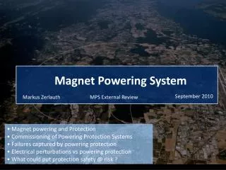
Protection System LHC Magnets The Protection System for the Superconducting Elements of the Large Hadron Collider at CERN K. Dahlerup-Petersen1, R. Denz1, J.L. Gomez-Costa1, D. Hagedorn1, P. Proudlock1, F. Rodriguez-Mateos1, R. Schmidt1 and F. Sonnemann2
STANDARD LHC HEATER POWER SUPPLIES QUENCH HEATER EXPERIMENTS ON THE LHC MAIN SUPERCONDUCTING MAGNETS F. Rodriguez-Mateos, P. Pugnat,S. Sanfilippo, R. Schmidt, A. Siemko, F. Sonnemann Supply based on the thyristor-triggered discharge of aluminium electrolytic capacitors. Each power supply contains a bank with 6 capacitors (4.7 mF/500V) where two sets of 3 parallel capacitors are connected in series total capacitance 7.05 mF Nominal operating voltage 450 V (90 % of the maximum voltage) OPERATION: Peak current about 85 A, giving a maximum stored energy of 2.86 kJ Actual limitations in terms of current Power supply equipped with two SKT80/18E type thyristors rated for 80 A at 85 ˚C. Maximum current for continuous operation = 135 A Peak current at 25 ˚C for 10 ms=1700 A (it will probably destroy the PCB of the power supply) Can be safely operated up to 300 A (resistive load in LHC from 12Ω in most of the circuits to 3.1 Ω in some systems such as D1 protection )
Impact of insulation material/thickness Kapton G10 Thermal conductivity Heat capacity https://espace.cern.ch/roxie/Documentation/Materials.pdf
ROXIE Thermal Network Lumped thermal network model in comparison to the coil/conductor geometry Tbath GijT,heater2coil GijT,heater2bath GijT,heater2coil
Tmaxvs MIITs Experimental Results and Analysis from the 11T Nb3Sn DS Dipole G. Chlachidze, I. Novitski, A.V. Zlobin (Fermilab) B. Auchmann, M. Karppinen (CERN) “To keep the cable temperature during a quench below 400 K, the quench integral has to be less than 19-21 MIITs“