QXF magnet design and plans
280 likes | 543 Vues
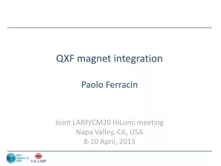
QXF magnet design and plans. G. Ambrosio and P. Ferracin. HiLumi -LHC/LARP Conductor and Cable Internal Review 16-17 October 2013 CERN. Outline. Overview of magnet design Strand parameters Cable dimensions (first iteration) Insulation thickness Coil design and cable unit lengths

QXF magnet design and plans
E N D
Presentation Transcript
QXF magnet design and plans G. Ambrosio and P. Ferracin HiLumi-LHC/LARP Conductor and Cable Internal Review 16-17 October 2013 CERN
Outline Paolo Ferracin Overview of magnet design Strand parameters Cable dimensions (first iteration) Insulation thickness Coil design and cable unit lengths Short sample current and magnet parameters Planning for short and long models Risk analysis
QXF magnet design Paolo Ferracin • Target: 140 T/m in 150 mm coil aperture • OD: 630 m • SS shell, 8 mm for LHe containment • Al shell, 29 mm thick • Iron yoke • Cooling holes • Slots of assembly/alignment • Master plates • 58 mm wide bladder • Iron pad • Aluminum bolted collars • Coil alignment with G10 pole key • Ti alloy poles
From HQ to QXF QXF HQ Paolo Ferracin • Similar coil lay-out • 4-blocks, 2-layer with same angle • Wider cable (from 15 to 18 mm), same stress with +30% forces • Same structure concept with additional accelerator features • Pre-load capabilities of HQ design qualified and successfully tested • Larger pole key for cooling holes, cooling channels, alignment – assembly - handling slots, LHe vessel
Engineering design(work in progress) Paolo Ferracin
Strand(from CERN technical specification document) RRP strand PIT strand Paolo Ferracin • 0.85 mm strand • OST RRP • 108/127, 132/169 and 144/169 • Bruker PIT • 192filaments • Cu/Sc: 1.2 55% Cu • For 108/127 and 144/169: 1.13 • Maximum critical current at 4.2 K • 361 A at 15 T • 632 A at 12 T
RRP cable PIT cable Paolo Ferracin
Cable insulation Paolo Ferracin • AGY S2-glass fibers66 texwith 933 silane sizing • 32 (CGP) or 48 (NEW) coils (bobbins) • Variables: # of yarn per coil and of picks/inch • Target: 150 μm per side
2D magnetic design(By F. Borgnolutti) Paolo Ferracin • Two-layer – four-block design • Analytical model with sector coil • 6 angles to optimize for field quality • Criteria for the selection • Maximize gradient and # of turns (protection) • Distribute e.m. forces and minimize stress • Result: 22+28 = 50 turns • All harmonics below 1 units at Rref = 50 mm
Lengths Paolo Ferracin
Superconductor properties and Iss computation Paolo Ferracin • Non-Cu Jcof virgin strand without self field (s.f.) correction • 2450 A/mm2(12 T, 4.2 K) • 632 A • 1400 A/mm2 (15 T, 4.2 K) • 361 A • Self field corr. (ITER barrel) • 0.429 T/kA • 5% cabling degradation • Godeke’s parameterization
Magnet parameters Paolo Ferracin • Operational conditions: 140 T/m • Iop: 17.5 kA • Bpeak_op: 12.1 T • 82% of Issat 1.9 K • Gss: 168 T/m • Iss: 21.2 kA • Bpeak_ss: 14.5 T • Stored energy: 1.3 MJ/m • Inductance: 8.2 mH/m
SQXF status and plan Paolo Ferracin • First generation cable in 06/2013 • Coil design with 1st generation cable in 07/2013 • Coil parts fabrication/optimization in progress • Decision on end parts for first generation coils: 01/2014 • Coil tooling • Winding and curing tooling by 11/2013 • Reaction and impregnation tooling by 02/2014 • Fabrication of full practice coil starts, both at CERN and in the US, in 02/2014 (with 1st gen. cable) • 2nd gen. cable by 06/2014 • 2nd gen. coil fabr. starts in 03/15 (LARP) and 05/15(CERN)
SQXF plan and scheduleCoil fabrication • CERN • 1st gen. cable • 2 practice coils • 1 mirror coil • 5 RRP coils • 2nd gen. cable • 6 PIT coils • 5 RRP coils • LARP • 1st gen. cable • 2 practice coils • 1 mirror coil • 5 RRP coils • 2nd gen. cable • 5 RRP coils Paolo Ferracin
SQXF plan and scheduleCoil fabrication Paolo Ferracin
SQXF plan and scheduleTests Paolo Ferracin • 1st generation coils • First LARP coil mirror test in 12/2014 • First CERN coil mirror test (mirror) in 04/2015 • First magnet test (SQXF1) in 05/2015 • Assembled and tested by LARP with 3 LARP coils and 1 CERN coil • Then SQXF1b (LARP), SQXF2 (CERN), SQXF2b in series (2015-2016) • All the coil fabricated to date will be available for 1 magnet (not shared) • Test of LHe containment in SQXF2b • 2nd generation coils • LARP RRP: SQXF3and SQXF3b (2016) • CERN PIT: SQXF4 (2016-2017) • CERN RRP: SQXF5 (2017) • Test of 2-magnets in 1-cold-mass: SQXF6 (2017)
CERN long modelsSchedule Paolo Ferracin • Coil winding starts in 09/2015 • 3 practice, 6 RRP, 6 PIT • Mirror test in end 2016 / early 2017 • First long model by mid-2017 • 2 long models, 4 tests in 2017-2018
LARP long modelsSchedule | 2015 | 2016 | 2017 | Paolo Ferracin • Coil winding starts in December 2014 • Mirror test in September 2015 • First LQXF test in August 2016 • 3 LQXF tested by end of 2017
Cable Compaction - Risk Analysis:Winding stability vs. Sheared sub-elements †Based on HQ02/03 and 11T coil fabrication data Paolo Ferracin
Cable Compaction - Risk Analysis:Winding stability vs. Sheared sub-elements †Based on TQ34, TQ35, LQ15 coils; ~12 x-sections per coil Paolo Ferracin
Additional slides Paolo Ferracin
3D magnetic design(By S. Izquierdo Bermudez, 1PoAN-04) HQ-type QXF Paolo Ferracin • From 4 (HQ) to 6 blocks in the ends • Impact on field quality: b6 < 1.1 unit and b10 < 0.2 unit • Iron pad removed with reduced length • 1% peak field margin in the end • Short model • Magnetic length 1.2 m • Coil length: 1.5 m • Good field quality region: 0.5 m
Mechanical analysis(by M. Juchno) Inner layer Outer layer Paolo Ferracin • Optimization of dimensions and locations of new features • ≥2 MPaof contact pressure at up to 155 T/m (~90% of Iss) • Peak coil stress: -160/-175 MPa • Coil displ. from start to nominal grad. • Radial/azimuth.: -0.3/-0.04 mm • Effect on field quality: 0.75 units of b6
Quench protection(see T. Salmi, 2PoCC-03, and G. Manfreda, et al., 2PoCC-05) Rdump = 46 mΩ Vmax= 800 V Vmax= 400 V Paolo Ferracin • Trace with 4 heaters strips per coil, with 50 μm polyimide insulation • Heating stations in outer layer only • Heater delay of about 17 ms • Before, 10 msof validation and, after, 20 msof outer-to-inner delay • Hot spot T of 350 K (34 MIITS) hardly achieved with no margin • Under study • Modelling of material properties (bronze) and quench-back + dI/dteffects • Reduced delay of heater (25 m polyimide?) and inner layer quenching
SQXF plan and scheduleCoil fabrication • CERN • Fabrication steps • Winding + curing + reaction + impregnation • Fabrication time • ~100 days (5 months) per coil • 1 coil produced • every 2 months in the 1st year • every 1.5 months in the 2styear • every 1 months in the 3styear • LARP • Fabrication steps • First generation • FNAL & LBNL: winding + curing • BNL & FNAL : reaction + impregnation • Second generation • LBNL on SQXF • FNAL and BNL on LQXF • Fabrication time • ~100 days (5 months) per coil • 1 coil produced every month Paolo Ferracin
Engineering design(work in progress) Centre of the magnet Centre of the aluminium shell Paolo Ferracin
Additional 1% to 2% from higher Tcm* Paolo Ferracin