Lenses and Imaging (Part I)
490 likes | 733 Vues
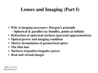
Lenses and Imaging (Part I). • Why is imaging necessary: Huygen’s principle – Spherical & parallel ray bundles, points at infinity • Refraction at spherical surfaces (paraxial approximation) • Optical power and imaging condition • Matrix formulation of geometrical optics

Lenses and Imaging (Part I)
E N D
Presentation Transcript
Lenses and Imaging (Part I) • Why is imaging necessary: Huygen’s principle – Spherical & parallel ray bundles, points at infinity • Refraction at spherical surfaces (paraxial approximation) • Optical power and imaging condition • Matrix formulation of geometrical optics • The thin lens • Surfaces of positive/negative power • Real and virtual images MIT 2.71/2.710 09/15/04 wk2-b-1
Parabloid mirror: perfect focusing (e.g. satellite dish) f: focal length MIT 2.71/2.710 09/15/04 wk2-b-2
Lens: main instrument for image formation air glass air optical axis Point source (object) Point image The curved surface makes the rays bend proportionally to their distance from the “optical axis”, according to Snell’s law. Therefore, the divergent wavefront becomes convergent at the right-hand (output) side. MIT 2.71/2.710 09/15/04 wk2-b-3
Why are focusing instruments necessary? • Ray bundles: spherical waves and plane waves • Point sources and point images • Huygens principle and why we can see around us • The role of classical imaging systems MIT 2.71/2.710 09/15/04 wk2-b-4
Ray bundles point source spherical wave (diverging) wave-front ⊥ rays point source very-very far away wave-front ⊥ rays plane wave MIT 2.71/2.710 09/15/04 wk2-b-5
Huygens principle Each point on the wavefront acts as a secondary light source emitting a spherical wave The wavefront after a short propagation distance is the result of superimposing all these spherical wavelets optical wavefronts MIT 2.71/2.710 09/15/04 wk2-b-6
Why are focusing instruments necessary? incident light ... is scattered by the object object MIT 2.71/2.710 09/15/04 wk2-b-7
Why are focusing instruments necessary? incident light ... is scattered by the object ⇒need optics to “undo” the effects of scattering, i.e. focus the light object image MIT 2.71/2.710 09/15/04 wk2-b-8
Ideal lens air glass air optical axis Point source (object) Point image Each point source from the object plane focuses onto a point image at the image plane; NOTE the image inversion MIT 2.71/2.710 09/15/04 wk2-b-9
Summary: Why are imaging systems needed? • Each point in an object scatters the incident illumination into a spherical wave, according to the Huygens principle. • A few microns away from the object surface, the rays emanating from all object points become entangled, delocalizing object details. • To relocalize object details, a method must be found to reassign (“focus”) all the rays that emanated from a single point object into another point in space (the “image.”) • The latter function is the topic of the discipline of Optical Imaging. MIT 2.71/2.710 09/15/04 wk2-b-10
The ideal optical imaging system optical elements object image Ideal imaging system: each point in the object is mapped onto a single point in the image Real imaging systems introduce blur ... MIT 2.71/2.710 09/15/04 wk2-b-11
Focus, defocus and blur Perfect focus Defocus MIT 2.71/2.710 09/15/04 wk2-b-12
Focus, defocus and blur Perfect focus Imperfect focus “spherical aberration” MIT 2.71/2.710 09/15/04 wk2-b-13
Why optical systems do not focus perfectly • Diffraction • Aberrations • However, in the paraxial approximation to Geometrical Optics that we are about to embark upon, optical systems do focus perfectly • To deal with aberrations, we need non-paraxial Geometrical Optics (higher order approximations) • To deal with diffraction, we need Wave Optics MIT 2.71/2.710 09/15/04 wk2-b-14
Ideal lens air air glass optical axis Point source (object) Point image Each point source from the object plane focuses onto a point image at the image plane MIT 2.71/2.710 09/15/04 wk2-b-15
Refraction at single spherical surface for each ray, must calculate • point of intersection with sphere • angle between ray and normal to surface • apply Snell’s law to find direction of propagation of refracted ray R: radius of spherical surface center of spherical surface medium 1 index n, e.g. air n=1 MIT 2.71/2.710 09/15/04 wk2-b-16
Paraxial approximation /1 • In paraxial optics, we make heavy use of the following approximate (1st order Taylor) expressions: where ε is the angle between a ray and the optical axis, and is a small number (ε «1 rad). The range of validity of this approximation typically extends up to ~10-30 degrees, depending on the desired degree of accuracy. This regime is also known as “Gaussian optics” or “paraxial optics.” Note the assumption of existence of an optical axis (i.e., perfect alignment!) MIT 2.71/2.710 09/15/04 wk2-b-17
Paraxial approximation /2 Ignore the distance between the location of the axial ray intersection and the actual off-axis ray intersection Apply Snell’s law as if ray bending occurred at the intersection of the axial ray with the lens Valid for small curvatures & thin optical elements off-axis ray axial ray MIT 2.71/2.710 09/15/04 wk2-b-18
Refraction at spherical surface Refraction at positive spherical surface: Power x: ray height α: ray direction R: radius of curvature off-axis ray optical axis MIT 2.71/2.710 09/15/04 wk2-b-19
Propagation in uniform space Propagation through distance D: x: ray height α: ray direction off-axis ray optical axis MIT 2.71/2.710 09/15/04 wk2-b-20
Paraxial ray-tracing air air glass Free-space propagation Free-space propagation Refraction at air-glass interface Refraction at glass-air interface Free-space propagation MIT 2.71/2.710 09/15/04 wk2-b-21
Example: one spherical surface, translation + refraction + translation R: radius of spherical surface Paraxial rays (approximation valid) center of spherical surface Non-paraxial ray (approximation gives large error) medium 1 index n, e.g. air n=1 MIT 2.71/2.710 09/15/04 wk2-b-22
Translation + refraction + translation /1 Starting ray: location x0 directionα0 Translation through distance D01 (+ direction): Refraction at positive spherical surface: MIT 2.71/2.710 09/15/04 wk2-b-23
Translation + refraction + translation /2 Translation through distance D12 (+ direction): Put together: MIT 2.71/2.710 09/15/04 wk2-b-24
Translation + refraction + translation /3 MIT 2.71/2.710 09/15/04 wk2-b-25
Sign conventions for refraction • Light travels from left to right • A radius of curvature is positive if the surface is convex towards the left • Longitudinal distances are positive if pointing to the right • Lateral distances are positive if pointing up • Ray angles are positive if the ray direction is obtained by rotating the +z axis counterclockwise through an acute angle optical axis +z MIT 2.71/2.710 09/15/04 wk2-b-26
On-axis image formation Point image Point object MIT 2.71/2.710 09/15/04 wk2-b-27
On-axis image formation All rays emanating at arrive at x2 irrespective of departure angleα0 MIT 2.71/2.710 09/15/04 wk2-b-28
On-axis image formation All rays emanating at arrive at x2 irrespective of departure angleα0 “Power” of the spherical surface [units: diopters, 1D=1 m - 1 ] MIT 2.71/2.710 09/15/04 wk2-b-29
Off-axis image formation Point object (off-axis) optical axis Point image MIT 2.71/2.710 09/15/04 wk2-b-30
Magnification: lateral (off-axis), angle Lateral Angle MIT 2.71/2.710 09/15/04 wk2-b-31
Object-image transformation Ray-tracing transformation (paraxial) between object and image points MIT 2.71/2.710 09/15/04 wk2-b-32
Image of point object at infinity Point image MIT 2.71/2.710 09/15/04 wk2-b-33
Image of point object at infinity object at ∞ image : image focal length Note: ambient refractive index at space of point image 1/Power MIT 2.71/2.710 09/15/04 wk2-b-34
Point object imaged at infinity Point object MIT 2.71/2.710 09/15/04 wk2-b-35
Point object imaged at infinity Image at ∞ object : object focal length Note: ambient refractive index at space of point image 1/Power MIT 2.71/2.710 09/15/04 wk2-b-36
Image / object focal lengths Point image Point object object at ∞ Image at ∞ Power Power MIT 2.71/2.710 09/15/04 wk2-b-37
Matrix formulation /1 translation by Distance D 01 refraction by surface with radius of curvature R ray-tracing object-image transformation form common to all MIT 2.71/2.710 09/15/04 wk2-b-38
Matrix formulation /2 Refraction by spherical surface Power Translation through uniform medium MIT 2.71/2.710 09/15/04 wk2-b-39
Translation + refraction + translation translation by D12 translation by D01 Refraction by r.curv. R result… MIT 2.71/2.710 09/15/04 wk2-b-40
Thin lens in air Objective: specify input-output relationship MIT 2.71/2.710 09/15/04 wk2-b-41
Thin lens in air Model: refraction from first (positive) surface + refraction from second (negative) surface Ignore space in-between (thin lens approx.) MIT 2.71/2.710 09/15/04 wk2-b-42
Thin lens in air MIT 2.71/2.710 09/15/04 wk2-b-43
Thin lens in air MIT 2.71/2.710 09/15/04 wk2-b-44
Thin lens in air Power of the first surface Power of the second surface MIT 2.71/2.710 09/15/04 wk2-b-45
Thin lens in air thin lens Lens-maker’s formula thin lens MIT 2.71/2.710 09/15/04 wk2-b-46
Thin lens in air thin lens Ray bending is proportional to the distance from the axis thin lens MIT 2.71/2.710 09/15/04 wk2-b-47
The power of surfaces • Positive power bends rays “inwards” Simple spherical refractor (positive) Plano-convex lens Bi-convex lens • Negative power bends rays “outwards” Simple spherical refractor (negative) Plano-convex lens Bi-convex lens MIT 2.71/2.710 09/15/04 wk2-b-48