P-326 TRIGGER/DAQ
This meeting discusses the key points of an all-digital trigger and data acquisition system, including reproducibility, integrated system, software scalability, and simplicity. Existing solutions and proposals for 11 MHz K decays + muon halo are also discussed.

P-326 TRIGGER/DAQ
E N D
Presentation Transcript
P-326 TRIGGER/DAQ Meeting with SPSC referees M. Sozzi - CERN – 14.11.2005
Mandatory key points • All digital trigger: reproducibility • All trigger information should be stored into the data flux • Integrated trigger-DAQ system • Software (and commodity) as much as possible: cost, flexibility, scalability, upgradeability • Simplicity and uncorrelated cuts USE EXISTING SOLUTIONS WHERE POSSIBLE
Reminder (proposal) 11 MHz K decays + muon halo (1) Simple hardware L0 1 MHz (2) Read-out of complete data into PCs(3) Single-subdetector software L1(4) Event building(5) Full-event software L2-L3(6) Tape logging in Computer Centre
Simulating L0 Estimate trigger rates from particle-level FLYO MC 6 main decay modes, normalized No muon halo yet Pion decay, bremsstrahlung, etc. Z vertex range: last collimator to hodoscope
No MAMUD hits (some small geometrical mismatch left in MC) 100% efficiency Gets rid of muon halo as well
No large-angle veto hits 14 pockets 100% efficiency
LKr total energy < 50 GeV Compatible with 40 GeV pion momentum cut Some model for hadronic shower in MC
Not more than 1 quadrants with energy (only counting deposits above 1 GeV) The condition should be fulfilled in at least 1 of 2 quadrant subdivisions rotated by 45 degrees(higher efficiency)
L0 rate estimate 11 MHz + halo 1 MHz 330 kHz Rate reduction to below 1 MHz seems achievable with “simple” and “local” information
Large-angle vetos OR(before any trigger) Muon halo NOT included Muon veto (before any trigger) Muon halo NOT included
What if… MAMUD is (online-) inefficient? BEWARE: No muon halo!!! Dangerous! Large angle vetos are (online-) inefficient? Likely irrelevant
Reminder & news • Discussion on L0 vs. triggerless solution:concept of a L0 (hardware) trigger (as in proposal): no triggerless approach • Would like to avoid zero suppression of FADC detectors (e.g. LKr if at all possible) • Looking into existing (LHC) solutions, trying to (1) adapt to them if possible(2) standardize among all sub-detectors
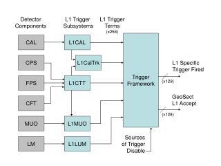
TRIGGERLESS MODEL - CONCEPT … HODO MAMUD ANTI LKR CEDAR STRAWS GIGA 1 MHz 1 GHz 10 MHz 50 MHz 10 MHz 10 MHz 10 MHz … L1 L1 L1 L1 L1 L1 L1 L1 L2 Full data Trigger data O(kHz) CDR L3 Trigger
L0 MODEL - CONCEPT … HODO MAMUD ANTI LKR CEDAR STRAWS GIGA 1 MHz 1 MHz 1 MHz 1 MHz 1 MHz L0 1 MHz … L1 L1 L1 L1 L1 L1 L1 L1 L2 Full data Trigger data O(kHz) CDR L3 Trigger
L0 MODEL - IMPLEMENTATION … HODO MAMUD ANTI LKR CEDAR STRAWS GIGA L0 … PC PC PC SWITCH PC PC PC PC PC PC PC CDR
Common electronics Subdetector For sure Analog FE Storage Try to do this! ADCTDC Global L1Trigger L2Trigger FPGA Very likely (if present) Local L1Trigger Switchfabric L1buffer FEbuffer L0Trigger
A possible concept • CEDAR, HODO, LKR, MU-VETO, ANTI, (RICH?) • Any subdetector involved in the L0 trigger provides digital, high-resolution hit/quadrant time information (w. walk/slewing corrections) – from main data TDCs, dedicated TDCs or on-board digital filters (all events) • All veto SD have FADC-like readout (frequency?) • L0 information is sent even asynchronously as lists of timestamps - within fixed maximum time after event, with synchronization frames sent periodically • L0 information is sent to L0 central processor which performs the sorting and matching, and delivers L0 trigger word (1 MHz) to initiate read-out to PCs
Implementation (TDC) FRONT-END TDC Packing and formatting L0 buffer Buffer manager & trigger matching TS list to L0 Data to PC TS from L0
Implementation (FADC) FRONT-END FRONT-END OR FADC, sum and time fit Sum & TDC FADC Packing and formatting Packing and formatting L0 buffer L0 buffer Buffer manager & trigger matching Buffer manager & trigger matching TS list to L0 TS list to L0 Data to PC Data to PC TS from L0 TS from L0
LHC-b TELL1 readout board • Interface to two different link systems; analog copper and digital optical. • Event synchronization, pedestal calculation and storage in the L1 buffer. • FPGA based digital signal processing as Common Mode Correction (CMS), clusterization (zero suppression). • Two data readout paths for L1T and HLT and data encapsulation into Ethernet, IP protocol based data frames. • Interface to the TTC system. • Experiment Control System (ECS) interface for controlling and monitoring. 30Gbit/s input data rate 4xGBit Ethernet To DAQ
TELL1 (cont.) • Could be the baseline solution for readout of ALL subdetectors, except:(a) SPIBES: will have VLSI dedicated front-end(b) LKr (with FADC): sheer data volume is too much for reasonable integration on TELL1Still: also the above could send digital data into TELL1 • CERN (CEDAR) and Mainz (STRAWS) started design of FADC and TDC daughterboards for TELL1. Pisa to test it as L0 central processor. • Lausanne group willing to collaborate (even for possible future upgrades, if required) • 2 boards will be made available for testing in Mainz and Pisa in 1 month (30 produced for LHC-b November 2005, 320 next year). 1 week training soon. • If adopted, we would need to arrange a production: some components might be problematic to find.
Indeed: proposal estimates done in ideal conditions: nominal K rate, particle level MC (flyo), perfect vetos • More realistic MC simulation of hit multiplicities in detectorsNeed improved MC (GEANT overkill) • Accidental simulation as a function of veto time resolutionWhich are the realistic online resolutions? MUON? VETO? • Define trigger capabilities of sub-detectors: HODO, RICH?, LKR,… SPSC referees’ questions
L0 (hardware): what will sub-detectors provide?Need the details of the sub-detector buffering stage.Could the central L0 processor be a PC? Could it be a LHC-b TELL1 board?“Super-events” will be needed • L1,L2 (software): ethernetHow to address the reliability issue? • Provide a conceptual design and let SD adapt to that… SPSC referees’ questions
A really tough one! (If we knew we would be largely done with trigger design…)However, it is true we should prove that a rejection power consistent with full beam rate and data logging rate.The difficulty depends on the level of sophistication (time) we can implement online.Need MonteCarloing of fast algorithms/cuts.Need timing tests on reconstruction algorithms. Sinergy with software WG… SPSC referees’ questions
… HODO MAMUD ANTI LKR CEDAR STRAWS GIGA 1 MHz 1 MHz 1 MHz 1 MHz 1 MHz L0 1 MHz … L1 L1 L1 L1 L1 L1 L1 L1 L2 O(kHz) CDR L3 SPSC referees’ questions L1 PCs for single sub-detectorsL2 PCs for complete event
SPSC referees’ questions This is mostly an issue only for L0 latency (rest is in PC memories). Make a conceptual design specifying the relevant numbers. Take as default the amount of buffer memory inside TELL1: 24 x 128 Mbit (need to know rates, occupancies).
SPSC referees’ questions Yes, definitely. The input to the L1 stage, full data triggered at 1 MHz. This is the most critical point identified so far.Lkr is the issue. Need to study (measure) LKr data compression.
Work in progress… The trigger/DAQ group focused so far on:- Overall architecture discussion- Identification of possible existing solutions- Early preparation for common solutions Some architectural points are now clear Some possible existing solutions have been identified, now starting to practice. Some actual designs started.
What’s next… The next stages are:- Tentative definition of TDAQ parameters (will need to iterate while sub-detectors are being defined) - Detailed simulation of L0 and L1,2 cuts and algorithms- Hardware tests on existing solutions
TELL1 (cont.) Powerful (5 FPGAs to do complex computations, on-board PCInterfaced to ethernet and to TTC clock/trigger system.Easily tested in standalone mode. Software available.
LHC-b trigger/readout supervisor Master controller 9U VME board, same backplane as TELL1 Works as: L0 trigger controller and broadcaster (TTC encoder)XOFF masterSlow-control interface Allows complete partitioning of read-out system for the experiment In production, software well developed, some components might be difficult to find in a few years from now But: LHC-b L0 trigger is synchronous, we are considering an asynchronous one…