Global Trigger Global Muon Trigger
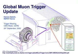
Global Trigger Global Muon Trigger. URL’s. This talk may be found at: http://wwwhephy.oeaw.ac.at/p3w/cms/trigger/globalTrigger/trans/wulz_AnnRev_sep01.ppt More detailed transparencies prepared by H. Sakulin about the Global Muon Trigger may be found at:


Global Trigger Global Muon Trigger
E N D
Presentation Transcript
URL’s This talk may be found at: http://wwwhephy.oeaw.ac.at/p3w/cms/trigger/globalTrigger/trans/wulz_AnnRev_sep01.ppt More detailed transparencies prepared by H. Sakulin about the Global Muon Trigger may be found at: http://wwwhephy.oeaw.ac.at/p3w/cms/trigger/globalMuonTrigger/trans/ GMT-IntReview24Sep2001.pdf More detailed transparencies about the Global Trigger prepared by A. Taurok and presented at the Trigger Meeting on Tuesday, 25 Sep. 2001, may be found at: http://wwwhephy.oeaw.ac.at/p3w/cms/trigger/globalMuonTrigger/trans/ GT_GTM_status_Sept01.ppt General information about the Global Trigger and the Global Muon Trigger is available at: http://wwwhephy.oeaw.ac.at/p3w/cms/trigger/globalTrigger http://wwwhephy.oeaw.ac.at/p3w/cms/trigger/globalMuonTrigger
Board Layout of the Global Trigger Processor PSB (Pipeline Synchronizing Buffer) Input synchronization GTL (Global Trigger Logic) Logic calculation FDL (Final Decision Logic) L1A decision TCS (Trigger Control System Module) Trigger Control NEW: L1A (Level-1 Accept Module) Delivery of L1A TIM (Timing Board) Timing GTFE (Global Trigger Frontend) Readout
Global Trigger Progress and Milestones • Milestone March 2002:System Test This includes the backplane, the PSB-6U, GTL-6U, FDL-9U and TIM-9U. The GTFE and the GMT are not included. • Backplane-6U: Prototype available • PSB-6U: available. Channel Link receivers used. • GTL-6U: Automatic chip design and setup procedure developed. Layout for a 20 channel GTL (4 , 4 isol. e/, 4 central jets, 4 fwd jets, SET, ETmiss, 8 jet multiplicities; other quadruplets can be connected alternatively for tests) is currently being finished. 1020-pin Altera FPGA 20k400E included for evaluation. The layout of a conversion board to be used later in final 9U-crate is ready. It contains also memories in FPGA’s to send simulated test data to the GTL-6U board. • FDL-9U: Design with 8 final OR’s in progress. • TIM-9U:The design of the board is nearly finished. The board contains a TTCrx chip and provides all timing signals for the GT crate. It will be used also in the Drift Tube Track Finder crates. An FPGA provides all necessary test functions to run the crate without the central TTC clock. It simulates also L1A requests for monitoring or to test the readout chain.
Global Trigger Progress and Milestones • Milestone July 2002:TCS-9U ready • TCS-9U: The main functions are defined but the design is still open for additional requests (calibration logic etc.) Trigger Partitions: The maximum number of subsystems is fixed (32). A preliminary agreement about the output to the DAQ Event Manager is has been reached. The input format of Fast Signals should be fixed soon. 5 coded bits per subsystem, sent as parallel data, are proposed. The TCS board provides data for the standard TTCvi as well as for a ”CMS-TTCvi”, but different interface boards are required. L1A driver module to be used with CMS-TTCvi has been conceived.
Global Trigger Progress and Milestones • Milestone October 2002: 9U backplane ready • The design with the GTLp 80 MHz and Channel Links is in progress. • Milestone June 2003: Complete GT prototype available • Integration tests possible from this date. • GTFE-9U: Conceptual design of readout board done. • Milestone July 2004:12-channel PSB-9U available • PSB-9U: Conceptual design done. Will have memories inside FPGA’s. • Milestone Nov. 2004: Complete GT available • Includes GTL-9U module with all 32 input channels (4 , 4 isol. e/, 4 non-isol. e/ , • 4 central jets, 4 forward jets, 4 t-jets, SET, ETmiss, 8 jet multiplicities). The Global Muon Trigger will have been completed by Nov. 2003.
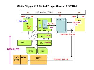
CaloTrigger RPC DTBX CSC BTI Bunch & Time ID CAL Readout Wire cards Strip cards Pipe-lined 40 MHz Warsaw TRACO Track Correlator PACT Pattern Comparator Motherboard Wisconsin Regional CALO Trigger Trigger Server HEPHY Vienna Florida CSC Endcap Track Finder DT Barrel Track Finder MIP &quiet bits (2x 252) Bristol Bari GLOBAL CALORIMETER TRIGGER RPC Sorter Bologna Rice DT Sorter CSC Sorter 4+4 4 4 HEPHY Vienna GLOBAL MUON TRIGGER 4 HEPHYVienna GLOBAL L1 TRIGGER L1 Accept ………… max. 100 kHz Global Muon Trigger
Tasks and Location of the Global Muon Trigger • Receive Muon Candidates from DT, CSC and RPC • Triggers • Find the best 4 muons in the detector • Make use of the complementarity of the muon trigger • systems(DT/RPCbarrel,CSC/RPCendcap) • increase efficiency • reduce ghosts • reduce trigger rate by improving pT assignment • Add MIP and Quiet bits from the calorimeter trigger • Forward best 4 muons to the Global L1 Trigger • GMT is located in the GT crate. It consists of 3 input boards (PSB) for the calorimeter information and 1 logic board. 3 additional slots used due to connectors.
Principle of the Global Muon Trigger • Inputs:8 bit f, 6 bit h, 5 bit pT, 1 bit charge, 3 bit quality • Further Inputs:MIP and Quiet Bits of252 calorimeter regions 3 programmable merging modes: winner/loser parameter selection parameter mixing • Output:8 bit f, 6 bit h, 5 bit pT, 1 bit charge, 3 bit quality, 1 bit MIP, 1 bit Isolation Responsible: H. Sakulin, A. Taurok, C.-E. Wulz
Global Muon Trigger Schedule • Milestones / Plans: • 2001 Logic design, ORCA + VHDL Simulation • Dec 2001 Logic design finished • 2002 VHDL Simulation, Design of FPGA chips • Dec 2002 FPGA design finished • 2003 Production of VME 9U Boards • 2004/05 Integration tests, production of spare boards
Progress towards GMT milestones • Dec 2001: Logic design finished • Progress in detailed logic design • Chip Models selected (mostly Virtex II), interconnections defined • Design compacted (external RAMs moved into big FPGAs) • Improvement of functionality • DT/CSC cancel-out unit (improved performance in barrel/endcap overlap region) • in parallel: • ORCA simulation extended and improved • Continuous studies to optimize GMT design parameters and performance • CMS Note 2001/003 published: H. Sakulin, M. Fierro, “Studies of the Global Muon Trigger Performance” • Detailed GMT design document in preparation • VHDL behavioral level simulation has started • Dec 2002: FPGA design finished • FPGA models have been selected • Synthesis tools are being evaluated
Simulation - muon 2001 production ORCA 5.1.2 • GMT optimized as in ORCA 5.1.2 • rate at 20 GeV/c: 3.1 kHz • L1 efficiency(*): 96.6 % • re-tuned GMT selection: • Only three-station CSC tracks used without RPC confirmation • rate at 20 GeV/c: 1.4 kHz • L1 efficiency(*): 96.3 % (*)efficiency to find muon of any pT in flat pT sample GMT single muon trigger rates (pT > 16 GeV/c) Rate from unconfirmed 2-station CSC tracks re-tuned GMT h
L1 efficiency with retuned GMT ORCA 5.1.2eff= 96.6%re-tunedeff= 96.3 % GMT efficiency to find any muon in a flat pT sample as in ORCA 5.1.2 w/o RPC noise Efficiency/% Efficiency contribution from CSC Q2 muons (lost with re-tuning)
Single muon rates • Trigger rate at 20 GeV/c (re-tuned GMT) • 1.4 kHz (last year: 2.9 kHz) • Generated rate at 20 GeV/c • ~120 Hz (last year: ~200 Hz)
GT and GMT Manpower • System Engineer: A. Taurok • CERN Doctoral Student: H. Sakulin (Logic and Hardware Design of GMT) • Technicians: (shared with DTTF and other activities) H. Bergauer, M. Padrta, K. Kastner (in Vienna) Ch. Deldicque (at CERN) • Physicists: M. Fierro, A. Jeitler, C.-E. Wulz (mainly working on GT/GMT) N. Neumeister, P. Porth, H. Rohringer, L. Rurua (partly working on other activities) L. Boldizsar (GT simulation, about 4 months per year in 2001 and 2002)
Conclusions • Progress in hardware design as planned • Global Trigger: Layout of GTL-6U almost ready Timing module designed Other modules also on track Design of TCS system updated • Global Muon Trigger: FPGA chips selected Design compacted New solution with one logic board VHDL simulation has started
Conclusions • New simulation results with muon 2001 production for Global Muon Trigger • pT-cut was lower than in last year’s production • improved CSC trigger & GMT can cope with higher background rate • trigger rates with improved trigger are lower despite higher background (even after taking into account the changed sample normalization)