GLOBAL TRIGGER
Explore the detailed layout, milestones, and prototypes of the Global Trigger Processor Board, along with the Global Trigger Logic and Final Decision Logic. Gain insights into synchronization, timing, and control systems for enhanced functionality.


GLOBAL TRIGGER
E N D
Presentation Transcript
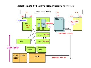
Board Layout of the Global Trigger Processor PSB (Pipeline Synchronizing Buffer) Input synchronization (7 boards including GMT) GTL (Global Trigger Logic) Logic calculation (1-2 boards) FDL (Final Decision Logic) L1A decision (1 board) TCS (Trigger Control System Module) Trigger Control (1 board) NEW: L1A (Level-1 Accept Module) Delivery of L1A (1 board) TIM (Timing Board) Timing (1 board) GTFE (Global Trigger Frontend) Readout (1 board)
Global Trigger Milestones 2002 • Milestone March 2002:System Test -> Delayed to Oct. 2002 This includes the backplane, the PSB-6U, GTL-6U, FDL-9U and TIM-6U. The GTFE and the GMT are not included. • Milestone July 2002:TCS-6U tested -> Delayed to Oct. 2002 • Milestone Oct. 2002:Backplane-9U tested -> OK
Backplane-6U, PSB-6U • Backplane-6U: Prototype available • 80 MHz GTL-plus signals, Channel Links • 2mm connectors, 160 pin VME connectors • Power Supplies: +5V, +3.3V, +2.5V, +1.8V • PSB-6U: available. Channel Link receivers used. 1 Sync Chip for 2 channels. • Monitoring of all input bits for every BX • Synchronisation checks for every BX
PSB-9U • Memories inside FPGA for Readout: • 3-5 bx read by a L1A
GTL-6U • GTL-6U Automatic chip design and setup procedure developed. Layout for a 20 channel GTL (4 , 4 isol. e/, 4 central jets, 4 fwd jets, SET, ETmiss, 8 jet multiplicities; other quadruplets can be connected alternatively for tests) is currently being finished. 1020-pin Altera FPGA 20k400E not yet included. The layout of a conversion board to be used later in final 9U-crate is ready. It contains also memories in FPGA’s to send simulated test data to the GTL-6U board. A decision on a possible redefinition of jet input groups has been taken. It was decided to keep the present best 4 central jets, 4 forward jets and 4 t-jets and jet multiplicities for different ET thresholds. A new quantity HT giving the transverse energy sum of all good jets above threshold has been added. The exact definition of how to calculate the jet multiplicities (h-range) still has to be taken at the level of the calorimeter trigger. More than 8 values could be necessary.
GTL-9U New: HT
GTL-6U Prototype Schematics Design simplified, board available by Oct. 2002
FDL-9U Schematic and chip design in progress. Board available by Oct. 2002. • Monitoring of all algorithm and L1A bits • Prescaling of all algorithms • Trigger Mask • 8 L1A’s in parallel for partition modes • Input of up to 64 technical trigger bits from PSB possible
TIM-6U • TIM-6U:The board contains a TTCrx chip and provides all timing signals for the GT crate. It will also be used in the Drift Tube Track Finder crates. An FPGA provides all necessary test functions to run the crate without the central TTC clock. It simulates also L1A requests for monitoring or to test the readout chain. The schematic design is finished. The layout is on hold until May 2002 due to TTCrx jitter problems. We would prefer to keep the TTCrx as a mezzanine board with interconnections identical to current board. The final Timing Board will be 6U (previously 9U).
TCS-9U • TCS-9U: The main functions are defined but the design is still open for additional requests (calibration logic etc.). The board is expected by Oct. 2002. Trigger Partitions: The maximum number of subsystems is fixed (32). A preliminary agreement about the output to the DAQ Event Manager has been reached. The input format of Fast Signals is now fixed. 4 coded bits per subsystem, sent as LVDS parallel data, and RJ45 connectors are proposed. The TCS board provides data for the new ”CMS-TTCvi”. A L1A driver module to be used with the CMS-TTCvi has been conceived.
Global Trigger Milestones beyond 2002 • Milestone June 2003: Complete GT prototype available • Integration tests possible from this date. • GTFE-9U: Conceptual design of readout board done. • Milestone July 2004:12-channel PSB-9U available • PSB-9U: Conceptual design done. Will have memories inside FPGA’s. • Milestone Nov. 2004: Complete GT available • Includes GTL-9U module with all input channels (4 , 4 isol. e/, 4 non-isol. e/ , • 12 jet channels, HT , SET, ETmiss, jet multiplicities). The Global Muon Trigger will have been completed by Nov. 2003.
Global Trigger ORCA Simulation • The L1 Global Trigger System is simulated by an ORCA package (starting from ORCA version 5) • Trigger/L1GlobalTrigger • Hardware system features are simulated • …except Delta conditions (topological correlations among different classes of trigger objects) and new HT/jet counts • Persistency of trigger objects is provided • Official documentation is available on the usual ORCA Software description pages
Implementing an algorithm: syntax • Each algorithm is made up of particle blocks of different kind: • MU, EL, IE, CJ, FJ, TJ, ET, EM, JN • Each block is numbered to have a one-to-one connection with its own condition settings (up to 64 different blocks per particle can be set): • MU_00, EL_01, FJ_01, EM_63,... • An algorithm is a combination of particle blocks, connected by .AND. ( & ), .OR. (|) conditions: MU_00&EM_00 | EL_00&EM_00
Implementing an algorithm: syntax User can provide algorithms in three different ways: • Use the default implemented algorithms • Write a file named trigger_menu.dat • One algorithm per line • Blank line allowed • This overrides the default Trigger Menu algorithms • Add one algorithm to the default • Via adding a line in the .orcarcfile L1GlobalTrigger:Algorithm MU_00&EM_00|EL_00&EM_00
Implementing an algorithm: thresholds For each particle block, user must provide a list of conditions by the WriteThresholdutility • It is an interactive tool that writes a file for each specified block • Users are asked for which block they want to provide conditions and then they are asked to specify the conditions themselves • User can modify conditions for the default implemented algorithms • If WriteThresholdis not invoked for a certain block, the conditions for that specific block are set to the default values (now defaults are set to “don’t care” values)
L1GlobalTrigger output • The output of L1GT is the Level 1 Trigger Accept word, a string of 128 bits. Each bit corresponds to the output of one algorithm. • User can select whether to check the overall L1 accept “signal” or a specific algorithm bit
Persistency • The information for each trigger object is saved per event, in form of BitArray • 24 bit for each muon candidate • typedef BitArray(24) MuonDataWord • 32 bit for each calorimeter object (req. from L1Calo Group) • Actually in the code only 21 bit words are used, following the hardware specifications • typedef BitArray(21) CaloDataWord • L1Accept word is saved as well • BitArray(128)
Persistency • User code can access the particle information via L1GlobalTrigger methods: • CaloDataWord getElectrons(int i) • MuonDataWord getMuons(int i) • Methods are provided to ‘convert’ BitArray information into usual particle parameters (ET, pT, h,…) • The L1GlobalTrigger code itself can run on the database, updating it according to whether the user modified particle conditions/algorithm definitions
L1 GT Efficiency Studies for some Physics Channels • The samples for 4 channels have been: • generated with PYTHIA 6.136 (1000 events per channel) • simulated with CMSIM121 • Hit-formatted and digitized with ORCA_5_3_2 • Pile-up for high luminosity has been added • The samples have then been processed with L1GlobalTrigger • The thresholds for calculation of efficiencies of individual algorithms are taken as for calculation of muon, calo and combined rates by M. Fierro and P. Chumney for 4 different DAQ scenarios: 75 kHz, 50 kHz, 37.5 kHz, 25 kHz.
Samples used for current analysis H250:HSM WW ll (leptonic decay) MH= 250 GeV/c2 HSM WW ljj (semileptonic decay) H800:HSM WW ll (leptonic decay) MH= 800 GeV/c2 HSM WW ljj (semileptonic decay) SUSY1: l + Et miss. + jets TTH150: l +Et miss. + jets + -jet
Efficiencies are calculated for 4 different DAQ bandwidth scenarios: 75kHz, 50kHz, 37.5kHz, 25kHz 1. Algo single muon 27.48, 25.48,22.87, 22.07 2. Algo di-muon 12.34, 12.34, 13.24, 12.34 3. Algo muon-ieg 13.54, 13.14,11.63, 10.93 4. Algo muon-tau-jet 24.77, 23.87, 21.36, 19.36 5. Algo muon-any-jet 40.82, 38.62,34.90, 32.50 6. Algo muon-et_total 41.42, 39.21, 35.51, 33.10 7. Algo muon-et_miss 40.12, 37.91,34.30, 31.99 8. Algo single ieg 12.84, 12.84,12.84, 11.94 9. Algo di-ieg 4.01, 4.01,4.01, 1.60 10.Algo single tau-jet 51.05, 51.05,48.75, 39.72 11.Algo di-tau-jet 20.86, 16.95,18.45, 16.95 12.Algo single jet 96.79, 96.79, 94.28,94.28 13.Algo double jet 89.67, 89.67, 84.95, 84.95 14.Algo triple jet 66.50, 63.39, 63.39, 63.39 15.Algo quad jet 50.35, 34.50,34.50, 34.50 16.Algo ieg-any jet 30.99, 19.26,19.26, 19.26 17.Algo ieg-tau jet 20.06, 13.24,12.74, 12.24 18.Algo et_miss 87.56, 87.56, 87.56, 87.56 19.Algo ieg-et_miss 30.39, 15.04,15.04, 15.04 20.Algo any jet-et_miss 96.29, 93.18, 93.18, 93.18 21.Algo et_total 83.75, 83.75, 83.75, 83.75 Total efficiency: 99.8, 99.7,99.4, 99.2% SUSY1lepton + ETmiss + jets
Efficiencies are calculated for 4 different DAQ bandwidth scenarios: 75kHz, 50kHz, 37.5kHz, 25kHz 1. Algo single muon 26.9, 25.6,22.9, 22.1 2. Algo di-muon 6.8, 6.8, 7.4, 6.8 3. Algo muon-ieg 12.7, 11.9,10.9, 10.1 4. Algo muon-tau-jet 19.7, 18.9, 17.8, 14.5 5. Algo muon-any-jet 16.2, 15.4,14.7, 13.8 6. Algo muon-et_total 19.1, 18.0, 16.8, 15.5 7. Algo muon-et_miss 21.9, 21.2,20.2, 19.1 8. Algo single ieg 21.6, 21.6,21.6, 19.0 9. Algo di-ieg 5.5, 5.5,5.5, 1.8 10.Algo single tau-jet 46.1, 46.1, 41.2, 24.8 11.Algo di-tau-jet 17.2, 10.5,12.5, 10.5 12.Algo single jet 33.2, 33.2, 19.7,19.7 13.Algo double jet 17.4,17.4,9.9,9.9 14.Algo triple jet 8.6, 6.7, 6.7, 6.7 15.Algo quad jet 7.6, 2.0,2.0, 2.0 16.Algo ieg-any jet 20.9, 16.3,16.3, 16.3 17.Algo ieg-tau jet 29.1, 23.1,20.1, 18.2 18.Algo et_miss 14.4,14.4,14.4,14.4 19.Algo ieg-et_miss 23.6, 15.1,15.1, 15.1 20.Algo any jet-et_miss 52.7, 27.3, 27.3, 27.3 21.Algo et_total 3.0,3.0,3.0,3.0 Total efficiency: 86.5, 79.9, 76.6, 70.8% l +ETmiss + jets + -jet
~ ~ l±-> c10l± Sleptons m+m- + ET miss + no jets This channel has been generated and processed with ORCA_6_0_1 The efficiencies for best 3 algorithms for 4 different DAQ scenarios are: single muon 96.3%, 96.0%, 95.6%, 95.2% di-muon 74.0%, 74.0%, 74.8%, 74.0% muon-ETmiss 14.2%, 14.2%, 14.2%, 14.2% TOTAL EFFICIENCY 96.8%, 96.6%, 96.4%, 96.3%
URL’s This talk may be found at: http://wwwhephy.oeaw.ac.at/p3w/cms/trigger/globalTrigger/trans/wulz_CPT_apr2002.ppt Other talks relevant to the Global Trigger presented during the April 2002 CPT week: http://cmsdoc.cern.ch/cms/TRIDAS/tr/0204/GT_status_April02.pdf (Trigger Meeting, A. Taurok) http://cmsdoc.cern.ch/cms/TRIDAS/calwg/Meeting_170402/TCS_functions_Apr02.pdf (Calibration Working Group, A. Taurok) General information about the Global Trigger and the Global Muon Trigger is available at: http://wwwhephy.oeaw.ac.at/p3w/cms/trigger/globalTrigger http://wwwhephy.oeaw.ac.at/p3w/cms/trigger/globalMuonTrigger
Conclusions Progress in hardware design PSB-6U and backplane-6U ready Layout of GTL-6U in progress, conversion board for 9U crate ready Timing module designed, waiting for layout L1A Driver Board conceptual design ready FDL module and backplane-9U expected in October 2002 Design of TCS system updated, TCS module expected in Oct. 2002 Crate and rack layout updated GT software incorporated in ORCA 6 Effiency studies performed for sample physics channels