Download
1 / 22
220 likes | 403 Vues
Global Trigger Review Nov 2007. Firmware, Hardware. Descriptions, schemes, user guides on Global Trigger Web page: http:// wwwhephy.oeaw.ac.at/p3w/electronic1/GlobalTrigger/GlobalTriggerCrate.htm. Presented for the Vienna group by A. Taurok.

E N D
Global Trigger Review Nov 2007 Firmware, Hardware Descriptions, schemes, user guides on Global Trigger Web page: http://wwwhephy.oeaw.ac.at/p3w/electronic1/GlobalTrigger/GlobalTriggerCrate.htm Presented for the Vienna group by A. Taurok H. Bergauer, C. Hartl, M. Jeitler, K. Kastner, I. Mikulec, B. Neuherz, M. Padrta, T. Schreiner, J. Strauss, C.E. Wulz
Firmware status: ok, Versions: VME64x chip V1012 VME chip V100e TIM chip V0016 TIM Timing board • Input: • DTFF: TTCrq : clk, l1a, bgo cmds(bcres, resnyc, res_evnr...) • GT: ECL : clk, bcres; from TCS: bgo cmds(bcres, resnyc, res_evnr...) • Output: • LVDS signals to all boards in crate: clk, l1a, bgo cmds(bcres, resnyc, res_evnr...) • Front panel clock BCRES delay up to 1 orbit for TTCrx and ECL input. Individual programmable delays for connected boards. Special delay for TCS board. • Clock options for backplane: • internal quartz oscillator • Differential clock from QPLL • Clock from TTCrx chip • PLL for front panel clock outputs Simulation BC-table for Bgo commands: Bcres, Resync, ResEvnr....
PSB chip XC2V3000 Firmware status: ok, Versions: VME64x chip V1012 VME chip V1002 PSB chip V0006 PSB input boards • 8 serial data channels 8 x 16 bits at 80 MHz • 16x4=64 input bits (LVDS 40 MHz) ...alternative to 2 serial channels • output via backplane to GTL board (80 MHz GTLp signals) • GCT data (jets, e/g, transversal energy sums, jet numbers) • Totem trigger bits • Technical trigger bits (tests, calibration..) • M/Q bits for GMT • Logic functions: • Phase adjustment • Progammable delay • SIM/SPY memories • Readout: • Ringbuffer • Derandomizing FIFO • Readout Processor • Channel Link output • Data check with reference memory • Configuration: JTAG-VME
0 1 0 Bit 15 12.5 ns 80 MHz 160 MHz S_0 S_1 S_2 S_3 Pre_3 Bit 15 samples 0 0 1 1 1 1 0 XOR XOR XOR XOR increment 1 0 0 0 Phase counters # Counter content FF 1 0 0 PSB OVERSAMPLING Switching time between 3 and 0 select s_2
GTL logic board Firmware status: ok, Versions: VME64x chip V100C VME chip V1004 REC chip V1005 Input via backplane as 80 MHz GTLp signals - 4 muons from Global Muon Trigger, - Calorimeter and Totem trigger objects from PSB board Output: 128 Algo bits to FDL board • 3 Receiver chips: • SIM/SPY memories • 2 CONDITION chips: • All input data go to each FPGA • Variable trigger functions as defined by the GTGUI setup program. • Thresholds can be changed by software. CONDITION chip firmware depends from trigger setup.
GTL Trigger SETUP procedure (actual status) User GTGUI (java) Define trigger conditions and algorithms def.xml vhdl forms (predefined Conditions) GTS (c++) Make VHDL code of defined conditions variable vhdl files constant vhdl files vme.xml TS software Test program Make firmware (synthesize vhdl code). QUARTUS (Altera) thresholds pof, sof files Configure chip and load thresholds Configuration by JTAG_VME FPGA chip COND1,2
XC2V3000 Firmware status: ROP does not work correctly Versions: VME64x chip V1012 VME chip V1007 FDL chip V1009 FDL Final decision board Input: 128 Algo bits from GTL board 64 Technical trigger signals from 1 PSB board Output: 8 Fin_OR signals to TCS board • Functions: • For each trigger bit: • Prescaler • Rate counter • 8 Mask bits • 8 Veto mask bits (techn. Triggers) • 8 Final OR • SIM/SPY memory • Ringbuffer & Readout logic XC2V3000 XC2V4000 firmware: 16 16+nn bit prescale & trigger counters 128 128 + nn Algo Rates # per luminosity segment
GMT Global Muon Trigger board (1) Input: 40 MHz LVDS 8 RPC muons 4 DTTF muons 4 CSC muons Output: 80 MHz GTLp 4 muons to GTL Firmware status: ok, Versions: VME64x 0000_1012 4/2007 ROP 0000_1002 5/2007 SRT feed_0005 5/2006 LFF feed_0001 12/2006 LFB feed_0001 12/2006 AUF feed_0001 1/2006 AUB feed_0001 1/2006 INB beee_beee 1/2005 INC beee_beee 12/2005 IND beee_beee 12/2005 INF beee_beee 12/2005
GMT Global Muon Trigger board(2) INB, INC, IND, INF: PHASE synchronisation (oversampling) Programmable delay per muon SIM/SPY logic Ring-Buffer LFF, LFB: next page AUF, AUB: Assignment of MIP and Isolation bit to muons. LUTs: eta, phi, pt dependend SRT: Final Muon Sorter SIM/SPY logic Ring-Buffer ROP: VME interface Readout Processor (ROP): Fetches data from INxx and SRT chips and sends GMT record to Channel Link. (4 us per 3bx-event).
GMT Global Muon Trigger board(3) • LFF, LFB: • Unit conversion LUTs • Matching Unit: between RPC and DT/CSC muons • Cancel Out unit in LFF: fRPC-DT, CSC-DT, • Cancel Out unit in LFB: bRPC-CSC • Sort_Rank assignment for sorting: • High rank for matched muons. • Parameter merging (pt, eta, phi, sign, rank) • Sorting of Barrel resp. Forward muons
TTCrq (TTCrm)mezzanine SLINK64 EVM SLINK64 DAQ DAQ Record Builder EVM Record Builder GTFE Readout board Firmware status: final EVM tests VME64x chip V1012 VME chip V1003 DAQ chip V1023 EVM chip V000F BST interface ...to be tested!!! LEDs JTAG POWER +1.5V/5A +2.5V/3A GTFE board VME INTERFACE CLOCK BCR L1A RES VME160 GPS TIME ROP_EVM XC2V3000-4BF957 ZPACK 2mm Input: - 7 PSB boards DAQ chip - FDL_D, GMT DAQ chip - FDL_E, TCS EVM chip ROP_DAQ XC2V3000-4BF957 Channel Links ZPACK 2mm DS90CR288A fixing part added
GTFE Readout board • Chan_recvr: checks header bits, writes event into channel_FIFO, makes empty/warn50,warn75,full flag • ‚FIFO‘ = 16 bit/40 MHz 64 bits/80MHz • Daq(evm)_evnr_check compares for each channel the # of received events against # of L1As(reference). • Roc_daq(evm) : State machine provides all control signals to send an event record to to the Slink. • resets the CRC sum, • applies the Header words, • reads event data from the FIFOs of the active channels and sends them to the S-Link, • appends the Trailer word with the CRC sum. • Record_maker applies control signals at correct time. PSB part of roc_daq: Status_encoder GTFE status = DAQ+EVM status to TCS board • SIM/SPY memory • Monitoring of event data • Simulation events to S-link • Record length is constant. • without zero-suppression • depends from nr of BC • active channels(boards) See GT web page: GT_Readout_format.pdf
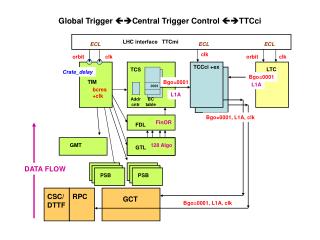
Global Trigger Central Trigger Control TTCci LHC interface TTCmi ECL ECL ECL clk clk orbit orbit clk TIM TCCci +ex LTC TCS bcres Bgo=0001 TCS_ delay Bgo=0001 0001 L1A L1A GTcrate_delay Addr cntr BC table Bgo=0001, L1A, clk bcres +clk FinOR FDL 128 Algo GMT 128 Algo GTL GTL DATA FLOW PSB PSB CSC/ DTTF RPC GCT Bgo=0001, L1A, clk
Firmware status: VME64x chip V100C VME chip V1004 TCSM chip V0002 (prototyp) TCS chip V0014 (final) TCS Central Trigger Control • TCS 2007 new features: • 8 PTCs (partition controller) for 8 DAQ partitions. • TCS event record: lum_segm_nr,... GT_Readout_format.pdf • Counter length extended to 32 resp. 40 bit. • One common 40 bit Orbit counter and one 16 bit Luminosity Segment counter for all PTCs. • Test measurements with independent PTCs may be related to each other offline. • Nr_of_Resync counter • New Bgo codes: ‚warn_test_en‘, ‚start_of_gap‘ • Hard_Res, Resync...by software only • L1A inhibited 2bx around Bgo commands. • Emulators: updated output code, additional delay for BCRES and Resync, simulation of status • Test trigger Multipartition readout mode: = standard default mode for tests and data taking L1A signals from all PTCs send GT_event records to the DAQ and to the EVM S-Link. PTC0 only controls the GT boards (bgo: resync, start, stop etc). PTC0 only resets the common Orbit and Luminosity Segment counter !!!! Status of GT&GMT boards goes to all PTCs. Status of GTFE(readout) board goes to all PTCs. See GT web page: TCS-9U-MODULE_2007.pdf Single partition readout mode: = only for special tests GT is connected to one PTC. DAQ and EVM records are sent only by L1A from this PTC. Status of GTFE and GT&GMT boards goes to this PTC only. Other PTCs are then disconnected from DAQ system, but still send their normal Bgo commands (BCRES, ...calibr. cycles...). But PTC0 resets the common Orbit counter and Luminosity Segment counter !!!!
16 bits ~ 68d (90s lum-segments) 32 bits 106 h = 4.4 d 32 bits 11.9h with 100 kHz trigger PTC0 only 32 bits PTC0 only 40 bits ~ 7.6 h PTC0 only
R) RATE COUNTER: # per lum_segment ACC) ACCUMULATING COUNTER: since start of run, resp. since last Resync +) while beam is active
Test procedures Interconnection tests: PSB GTL FDL GMT GTL FDL GTL FDL GTL contains builtin test logic switching input channels and ALGO bits to SPY memory and to Algo output pins, so that they can be spied also in the FDL board. GT_GMT_pattern.txt contains simulation data to be loaded into SIM memories and/or expected results which will be compared to the SPY memory contents. • Readout tests: ... GTFE • DAQ_FINOR readout test: • - Connect FEDKIT cable to the DAQ –S-Link • Load sim-data into GMT , PSB boards and set-up all registers. • TCS board forwards FinOR signals as L1A to the GT boards. • TCS: Start Run • Fedkit receiver program checks event records: CRC sums, trig_nr • Check also data in GTFE SPY memory if they agree with sim‘data of GMT, PSB boards. • DAQ_random_trigger readout test: Same test with random trigger from TCS board. • EVM_FINOR readout test: same test but S-Link connect to EVM chip • DAQ_random_trigger readout test: with random trigger from TCS board. Builtin and Single board tests: PSB: Loopback test, option with hardware data check to measure BERR 10-13. GMT: Load SIM mem‘s of INxx chips, read SPYmem‘s in SRT chip and compare with expected results. GTL: Load SIM mem‘s in REC chips and compare with content of SPY mem in COND chips.
Installation, cabling, commissioning • Vienna: 1 GT crate (permanently in Vienna) Maintenance • 1 GT crate (will be sent to Cern when testing has been finished) • TTCvi, TTCex, ClockModule, 1 FEDKIT for S-Link tests • Cern: 1 GT crate in CMS, • 1 GT crate (has to go back to Vienna to be modified!)