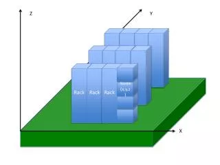
Global Trigger Rack
4. U Cross Flow Fan. Rack Layout according to CMS Standard. with Monitoring Unit. Rack: CMS-DISIR-IG-0002 v.2 (EDMS Id:. PCI-VME link. 114226). 2. U Heat Exchanger. 1U=1.75“=44.45mm. 56U racks, w=60cm,. 4 Tracker Emulators,. depth=90cm, h=256cm. 9U/6U crate. 8 Emulator. cables.

Global Trigger Rack
E N D
Presentation Transcript
4 U Cross Flow Fan Rack Layout according to CMS Standard with Monitoring Unit Rack: CMS-DISIR-IG-0002 v.2 (EDMS Id: PCI-VME link 114226) 2 U Heat Exchanger 1U=1.75“=44.45mm 56U racks, w=60cm, 4 Tracker Emulators,.. depth=90cm, h=256cm 9U/6U crate 8 Emulator cables other 6U_boards (standard VME backplane) 2 U Fan Unit JTAG 2 U Heat Exchanger 16 DT,CSC,RPC muon cables GMT, GT, TCS 12 cables MIP/QUIET bits 9U crate (non-standard backplane) 7 cables Calo trigger data +1 free cable trigger data 9kW cooling power 47U used 2 U Fan Unit 32 TTC_data (L1A,cmd) 3kW per crate 2 U Heat Exchanger 32 Subdetector STATUS cables Conversion boards 8 DAQ STATUS cables 9U/6U crate (Fast signals,...) 8 PTC STATUS cables (standard VME backplane) 2 U Fan Unit 2 U Heat Exchanger 2 S-links 2 U Air Flow Guide Note: PCs will actually be moved to top of rack PCs outside Air Flow DAQ -PC 2 opt. DAQ links less than 9 U used Online-PC Global Trigger Ethernet 56U Rack PrivateTest-PC A.Taurok 28 May 2003 Global Trigger Rack
Global Trigger Crate All boards on front side. Boards arranged for minimum cable length.
Global Trigger Prototype Crate GTL_CONV VME interface PSB PSB GTL6U
PSB-6U Prototype Board Synchronisation and monitoring of trigger data PSB6U only for the Prototype Crate VME interface ROP for DAQ Input module SYNC chips MEMORY
new PSB_IN80 for PSB-6U Registers for 40 80 MHz conversion 40, 80 MHz CLK drivers DS92LV16 receivers DS92LV16 transmitter for tests Infiniband connectors
GTL Conversion Board GTL_CONV is used only in the Prototype Crate VME interface VME to GTL6U +1.5V supply 80MHz GTL+ signals Channel Link signals ChannelLinkRec CONV chips
VME COND chips 4 muons 4x4 calo objects GTL+ signals REC chips GTL-6U Logic Board (right side) GTL6U will be used in the prototype crate as well as in the final GT-crate Calculates 64 trigger algorithms
TIM chip new TIM-6U Timing Module TIM-6U will be used in the prototype as well as in the final GT and DTTF crates. VME TTCrx CLOCK circuits LVDS drivers CLK, BCRES, L1A, RESET to each VME slot Front Panel
FDL-9U Final Decision Logic A.T. 21.2.03 VME FDL chip on MEZZ896 ALGO bits to DAQ ALGO bits to EVM Techn.Trigger bits from PSB ALGO bits from GTL Final OR bits to TCS
TCS-9U Central Trigger Control Board VME TCS status to 8 DAQ part‘s L1A,... to 32 TTCvi FastSigs from 8 Emulators EVM+DAQ records FastSigs 24 part‘s + 8DAQ part‘s TCS_MON chip TCS chip Clock
Mezzanine Board (MEZZ896) XC2V2000-4FF896C 50 Ohm connectors bottom side top side BGA: 1mm pitch, track width=83 mm MEZZ896 will be used in TCS-9U and FDL-9U
TTC units SIGNAL GENERATOR TTCvi TTCvx 100kHz-1GHz Global ECL AC clk_in clk_out Calorimeter Global Trigger clk_out clk_in Trigger orbit _out PSB + TIM IM TTC A PSBin80 A B rx optical B ECL fibre trans CLK clk_x NIM board return BGo command: 0001 bcres NIM rec orbit _x clk diff PECL Infiniband cable 1m / 5m Serial Link 1280 Mbps GCT-trigger data GCT/GT integration test setup Bristol + Vienna groups, Vienna, July 2003
GCT/GT integration test results and plans Link latency 50 ns with 1m cable, 65 ns with 5m cable. Data exchange 64 bits per 25 ns sent over one two-pair Infiniband cable. Different sets of patterns have been programmed at the transmitter end of the link and successfully read from a memory on the PSB. Clock PLL-based clock drivers to stabilize the TTC clock signals can be used. Long term stability Full test still to be made. 20000 LHC orbits equivalent to 5 . 109 bit cycles tested. Further tests Planned in Vienna with boards from Bristol in autumn 2003.
GT on-line and ORCA software C++ test programs exist to run the following boards both stand-alone and as a system : PSB-6U, GTL-CONV, GTL-6U, TIM-6U, TTCvi. The programs are being implemented as XDAQ-plugins. The GT setup definition is planned in .xml format, also to be used by ORCA. We are working on the SETUP program, including on a concept with a GUI.
Global Trigger Status and Milestones Sept. 2003 • Custom Backplane for VME 9U crate • 6U Prototype: Channel Links ... existsMS 03/02 • 9U Backplane: 80MHz GTLp and Channel Links, ... design in progress MS 03/03 09/03 12/03 • PSB Input board (synchronisation, monitoring) • 6 channel 6U Prototype: Channel Link receivers... board tested MS 03/02 • PSB-IN80:DS92LV16serial receivers... board tested • 12 channel board: memories inside FPGAs ...conceptual designMS 06/04 • GTL Logic board: • Conversion board for prototype ... board tested MS 03/02 • GTL-6U prototype: 20 channels …hardware is testedMS 06/03 • Signal transfer tested with test patterns -> ok … working on firmware • XDAQ compatible test program in C++ exists • Loading of conditions not tested yet (software under development) • GTL-9U board: 32 channels ...conceptual designMS 11/04 • 4, 4 isol. e/, 4e/, 4 central jets, 4 fwd jets, 4 t-jets, SET, ET mis, HT, 12 jet counts • TIM Timing board ... board testedMS 06/03 09/04 • 6U size, TTCrx, clock and L1A distribution, also used by DTTF; working on version for new TTCrx • MEZZ896 • Mezzanine boards(used on TCS-9U, FDL-9U)... boards produced MS 06/03 • FDL-9U Final Decision board... design in progress MS 06/03 11/03 02/04 • TCS-9U Central Trigger Control board... Layout finished MS 04/03 09/03 12/03 • GTFE-9U Readout board... conceptual design MS 12/03 03/04 02/05 Milestones updated
Global Muon Trigger FPGA design 12/03 Board production 06/04 GMT system tests 01/05 Production, Full Chain and Slice Tests, Integration Global Trigger Global Trigger PROTOTYPE BACK-6U ok PSB-6U ok PSB-IN80 ok GTL-CONV ok GTL-6U hardware tested (Milestone 6/03) TIM-6U done (Milestone 6/03) - prototype will be used as spare module for final system Integration test with GCT done (July 2003) GTL-6U hardware ok TIM-6U 09/04 (version for new TTCrx) TCS-9U 09/03 12/03 BACK-9U 09/03 12/03 FDL-9U 11/03 02/04 GTFE 03/04 02/05 PSB-9U 06/04 System test (full chain) of 20-channel GT (without GTFE) 06/04 Integration of GT/GMT with DAQ 01/06 Slice tests performed in Vienna as boards become available. Installation and commissioning in USC55 planned in phase with other subsystems (GCT, regional muon trigger systems) during second half of 2005. GTL-9U 11/04 GT system tests 6/05
Conclusions • GTL-6U Logic board produced and tested • TIM-6U Timing module produced and tested • TCS-9U Layout of TCS module finished • FDL-9U Final Decision Logic is in progress • PSB_IN80, GTL_CONV, MEZZ896 Auxiliary boards produced and tested • XDAQ compatible on-line software is under development • ORCA software is being updated