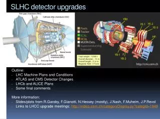
Global Trigger Upgrades for SLHC
Global Trigger Upgrades for SLHC. Vienna, Global Trigger Group A.Taurok , C.-E. Wulz SLHC Workshop, FNAL, 19 Nov. 2008. Global Trigger Concept for LHC and SLHC. Synchronize all Trigger Objects to arrive at the same time at the logic chip.

Global Trigger Upgrades for SLHC
E N D
Presentation Transcript
Global Trigger Upgrades for SLHC Vienna, Global Trigger Group A.Taurok, C.-E. Wulz SLHC Workshop, FNAL, 19 Nov. 2008
Global Trigger Concept for LHC and SLHC • Synchronize all Trigger Objects to arrive at the same time at the logic chip. • 2008 Version: Muons: done by GMT; Calo_objects: done by PSB; TechTrig: done by PSB • SLHC Version: Muons: done by GMT; Calo_objects:done by GCT; TechTrig: done by SYNC chip Tracker: done by Tracker_Trigger • Send all Trigger Objects into one chip to make any correlation between them. • Use a FPGA to change trigger conditions as required by physics • New trigger setup: configure FPGA with new trigger conditions • New parameter values for same setup: • 2008 Version: Load new ET or pT thresholds and prescale values by software • SLHC Version: Load all values by software • Calculate physics trigger algorithms in parallel (FPGA branch) • 2008 Version: 128 Algorithms limited by board layout, connectors and chip size • SLHC Version: Extend to ‘nn’ Algorithms ‘Algo’ signals inside chip Chip size will be the only restriction • Final OR mask for all Algorithm bits; Prescaler & Counter for each Algorithm • SLHC: some other requirement ?? • SLHC Version: • Array of DSPs for complex physics triggers • C++ code trigger program with constant latency(!) • 1 optical link for each trigger object of 64 bits/40MHz A. Taurok, C.-E. Wulz
CAEN VME CONTROLLER PC: RUN Control 1 FREE VME 2 FREE VME 3 4 L1A 5 L1A_OUT Detector subsystems L1A_OUT 6 aTTS DAQ APV-EMULATORS 7 TCS STATUS SIGNALS 8 TECHNICAL TRIGGER SIGNALS PSB 9 128 Algo FDL 10 GTL 11 LEVEL 1 GLOBAL TRIGGER 9U-VME CRATE Version 2008 12 spare Backplane 4IEG, 4EG, 4JET, 4fJET PSB 13 4TAU-JET, ET*, JetNr, PSB 14 (ET*=total ET, HT, MET) PSB 15 TOTEM CLK, ORBIT TIM 16 TTC - GPS-TIME S-links: DAQ, EVM GTFE 17 GMT 18 8 RPC muons 4 DT muons 4 CSC muons PSB 19 PSB 20 PSB 21 MIP/QUIET bits A. Taurok, C.-E. Wulz
COND ALGO COND ALGO Sync delay PSB REC Sync delay SYNC CMS Level1 Global Trigger scheme LHC GTL FDL Sync delay GMT 128 Algo GTL Final OR GCT Sync delay PSB Prescalers & Trigger Counters Technical Triggers Totem, Castor, ZDC, … SLHC COND chip Optical links FDL chip Sync delay GMT FPGA: Standard Conditions GTL nn Algo (and, or, not) Sync delay GCT COND chip Final OR - FPGA: DSPs (XC5V100T) Tracker Trigger Sync delay Tracker ‘Conditions’ Prescalers & Trigger Counters ‘Conditions’ Totem, Castor, ZDC, … A. Taurok, C.-E. Wulz
Input to Global Trigger • Global Calorimeter Trigger (GCT): possiblereduction of trigger data • 4 eg, 4 isol. eg(ET, h, f) eg’s with ISOLATION bit • 4 central jets, 4 forward jets(ET, h, f) jets • 4 tau jets • total_ET, HT apply set of thresholds in GCT • and send resulting bits to FDL chip • missing_ET (ET, f) • HF ring ETs, etc. • More than 4 objects per type: 5 or 6 (?) Simulation for SLHC • Global Muon Trigger (GMT): • 4 muons (pT, h, f, mip, iso, charge, quality) • Tracker Trigger: • Tracks/jets with h and f COND chips • ‘Conditions’ calculated in Tracker Trigger FDL chip A. Taurok, C.-E. Wulz
Single particle thr1, h, f window1 ieg1 ieg1 Single particle thr1, h, f window1 ieg2 ieg2 Single particle thr1, h, f window1 ieg3 ieg3 Single particle thr1, h, f window1 ieg4 ieg4 Single particle thr2, h, f window2 Single particle thr2, h, f window2 Single particle thr2, h, f window2 Single particle thr2, h, f window2 CMS Global Trigger standard Algorithm in FPGA: example Standard CONDITION chip Predefined VHDL code Missing Energy TEMPLATE ieg1 ieg3 Dh, Df Correlation TEMPLATE ieg2 ieg4 Single particle TEMPLATE Dh, Df Correlation ET thresholds 1,2 h, f window 1,2 Parameters Find 2 out of 4 particles fulfilling all conditions Missing Energy threshold IEG condition: ieg2wsc Missing ET condition: MET FDL chip Mask, Veto_mask Combinatorial logic: Algorithm = ieg2wsc and MET Final_OR ALGO bit (i) prescalers A. Taurok, C.-E. Wulz
CONDITION chip with DSP array, RISCs Trigger objects (GCT, GMT, TrackerTr…) Parameters Hardwired logic* DSP Condition program Latency = # of instructions XC5VFX100T: 256 DSP48E(550MHz), 4 Ethernet MAC, 3 PCIexpress end points, 16 GTX RocketIO (6.5Gb/s) 680 IO (1.25Gb/s LVDS) Condition bit *) if DSPs are implemented in FPGA • Constraints: • # of Conditions # of DSPs • # of instructions latency limit • Keep pipeline structure Parallel or tree structures Trigger objects Trigger objects DSP DSP DSP DSP DSP DSP Latency Latency DSP OR Condition bit Condition bit Algorithm logic in FDL chip Algorithmlogic in FDL chip A. Taurok, C.-E. Wulz
Spy_mem‘s & Ringbuffers Spy_mem‘s & Ringbuffers Control CPU Control CPU Event builder LVDS LVDS LVDS LVDS LVDS Prescalers Trigger Counters Global Trigger board for SLHC (‘Single board’ option) Ethernet IP DAQ chip Ethernet IO CMS - DAQ 2 sets of opt. rcvers Ethernet IP L1A_daq + Serial TX L1A_daq + Serial TX RX: Serial parallel COND_logic or DSP array nn Algo (and, or, not) LVDS Final OR Condition bits GCT: 5 ... GMT: 2 Tracker: ~2 .. COND chip Parallel data Sync circuits Condition bits FDL chip Ethernet IP TIMING circuits CLK, BCRES, ... CLK, BCRES, .. SYNC Chip Ethernet IP A. Taurok, C.-E. Wulz
12/16 12/16 12/16 12/16 16 16 16 16 20 20 20 20 FPGA FPGA FPGA FPGA 16 16 16 16 20 20 20 20 12/16 12/16 12/16 12/16 72x72 SWITCH 72x72 SWITCH 72x72 SWITCH 72x72 SWITCH Option with Custom MTCA backplaneGT logic with AMC single width module from Imperial College & LosAlamos Lab. GCT 2 copies of 7 quadruplets à 64 bits 3.2 Gbps optical links CONDITION CHIP 1+2 AMC single width (h=73.8 mm, l=181.5 mm) 7 TrackerTrigger 2 copies of ≤5 links à 64 bits Custom Backplane 5 1 Readout Board 512 Condition bits ALGO + FinOR (FDL) 2 128 Technical Trigger bits from Conversion crate 3.2 Gbps backplane links 1 8 Readout Board Partition STATUS from 2 Big_Conversion boards 8FinalOR 1 2 L1A..directly or via Big_Conversion boards to TTC system 4 1 • NOT shown/defined: • Global Muon Trigger • Readout board with SLINK • LVDS/Serial Conversion crate Readout Board 32x 8 (L1A, 5Bgo…) Central Trigger Control Readout Board as double width AMC with SLINK mezzanine board CMS_DAQ Readout data A. Taurok, C.-E. Wulz
FPGA FPGA FPGA FPGA FPGA MTCA options: 40 MHz LVDS to Serial Conversion AMC modules (Vienna) SMALL_CONVERSIONcardsingle width, full size (w=73.8 mm, l=181.5 mm, h=28.95 mm) 8 RJ45 (59.2 x 25.5 mm) INPUT MODE OUTPUT MODE Serial link (1.6 Gbps required) Serial link (1.6 Gbps required) 32 bits 32 bits Global Trigger: 128 Technical Trigger bits 4 SMALL_CONVERSIONboards (INPUT mode) Central Trigger Control: 40x4 STATUS bits 5 SMALL_CONVERSIONboards (INPUT mode) 8x4 EMULATOR CONTROL signals 1 SMALL_CONVERSIONboards (OUTPUT mode) 32x8 L1A+BGo signals 8 SMALL_CONVERSIONboards (OUTPUT mode) • Many boards!! • No front panel serial links CONVERSION card double width,full size (w=148.8 mm, l=181.5 mm, h=28.95 mm) LC duplex INPUT MODE OUTPUTMODE I/OMODE Serial link (3.2 Gbps required) Serial link (3.2 Gbps required) Serial link (3.2 Gbps required) 64 bits/40MHz Synchronization, Monitoring Monitoring 64 bits/40MHz 64 bits/40MHz Global Trigger: 128 Technical Trigger bits 2 CONVERSIONboards (INPUT mode) Central Trigger Control: 32x4 STATUS bits 2 CONVERSIONboards (INPUT mode) 8x4x2 EMULATOR CTRL+STATUS 1 CONVERSIONboards (I/O mode) 32x8 L1A+BGo signals 4 CONVERSIONboards (OUTPUT mode) • 9 boards • Serial links (3.2 Gbps) on front panel A. Taurok, C.-E. Wulz
Optical connectors MTP connector: 18 mm x 40(space on board); 11.2 mm from board edge to front side, h= 11mm without heatsink SFP+ connector: transcvr, w=13,7, L=56.5, h=8.6mm LC connector: w=4.52 mm, h=5.7 Duplex LC: 6.25mm middle-middle~14 mm Panduit MTP module: FC9-24-10Y or FCXO-… 24 single mode fibers9/125, 2mtp to 12 duplex LC, w = 88.9 mm. L=144.2, h=35.3 Avago optical transcvr: duplex LC with 6.25mm middle-middle; w= 14.9 or 13.6; h= 12.4mm double width AMC boards (h=148.8 mm, l=181.5 mm) Conversion board: AFBR-57R5AEZ 4.25 Gbps, 850nm VCSEL, SFP duplex LC (Lucent) 20x20mm FPGA 35x35mm A. Taurok, C.-E. Wulz
Option with Standard MTCA backplane: Crate examples Example: Single width shelf (Schroff/Pentair) Example: Double width shelf (Schroff/Pentair) Example: single width Cube (Elma) Mechanical problems Ruggedized crates from other suppliers: vibration, shock isolation A. Taurok, C.-E. Wulz Single width shelf
Option with Standard MTCA backplane: Example of standard MCH (MTCA carrier hub) module NAT-MCH (www.nateurope.com) Central management and data switching entity Fast Ethernet CPU management Giga-Ethernet uplink to backplane CPU:carrier-,shelf-, system manager Fabric D-G: Serial Rapid I/O (PICMG AMC.4) Fabric A: Gigabit Ethernet Fabric B: Serial Attached SCSI Clock mezzanine NAT-MCN Clock mezzanine Tundra TSi578 (Tundra Web page) RapidIO 1.25, 2.5, and 3.125 Gbits/s per port A. Taurok, C.-E. Wulz
Double width TCA board for GT double width,full size (w=148.8 mm, l=181.5 mm, h=28.95 mm) 181.5 mm • BLUE LINES: • ‘nn’ Serial links between FPGA • <1 Gbps ~ 16 bits à 40 MHz • ~32 parallel LVDS 40/80 MHz 3.2 Gbps RJ45 Port4(8) FPGA ~35x35mm MTP 12 REC ~18x40mm Port5(9) FPGA MTP 12 REC 3.2 Gbps • Port links between Boards • Speed depends on MCHUB 3.2 Gbps 1 Gbps 148.8 mm Port6(10) FPGA RJ45 Optional Ethernet MTP 12 REC Port7(11) MTP 4 REC, 4 TX CTRL FPGA 3.2 Gbps Port0,1 MTP 4 REC, 4 TX POWER JTAG CLOCK A. Taurok, C.-E. Wulz
COND1 FPGA IN+LFB FPGA IN+LFF FPGA CTRL FPGA FDL FPGA AU FPGA Option with Standard MTCA backplane:GMT+GT crate with double width AMC modules (Vienna) 3.2 Gbps MCH1 fat pipe (Readout) GMT Global Muon Trigger Port4(8) CSC+fRPC 8 muons 4 12 Standard Backplane Port5(9) 8 4+4+2 GCT 504 M+Q bits 12 4 12 Port6(10) DT+bRPC 8 muons double width AMC boards (h=148.8 mm, l=181.5 mm) Port7(11) 1 SRT+ CTRL Readout board 4 8r8tx port0,1 to GTL 4 muons MTP connector: 12 fibers rec/tr 18 mm x 40 mm GCT 2 copies of 7 quadruplets á 64 bits ALGO(GTL) + FinOR (FDL) 2 Port4(8) 12 7 Port5(9) 12 TrackerTrigger 2 copies of ~2 links à 64 bits 2 12 Port6(10) 2 COND2 FPGA spare Port7(11) 1 Readout board 8r8tx • 8FinalOR • Central Trigger Control port0,1 1 128 Technical Trigger bits parallel LVDS 1 2 CONVERSION cards MCH2 fat pipe (Trigger data) Readout Board CMS_DAQ SLINK A. Taurok, C.-E. Wulz
xxx FPGA xxx FPGA TCS FPGA Option with Standard MTCA backplane:Central Trigger Control Crate MCH1 fat pipe (Monitoring) double width AMC boards (h=148.8 mm, l=181.5 mm) Central Trigger Control & Readout Port4(8) Standard Backplane 12 Port5(9) 4+4+2 12 1 8FinalOR 12 Port6(10) 1 2 Port7(11) TCSM+ CTRL Readout board 1 8r8tx port0,1 4 32x 8 (L1A, 5Bgo…) Readout Board with SLINK mezzanine board to be defined. 2 Partition STATUS Parallel LVDS CONVERSION card input mode L1A, BGo… to TTC 32 x 8 signals CONVERSION card output mode EMULATORs 8x 4 bits status bits 8x 4 bits control signals CONVERSION card I/O mode Control data: Bgo, L1A, Resync, Bcres… MCH2 fat pipe (Control data) 32x 8 (L1A, 5Bgo…) Central Trigger Control A. Taurok, C.-E. Wulz
Conclusions • Basic design idea for an upgraded Global Trigger exists. • First idea was a VME implementation, using DSP’s. • Implementation in MTCA technology now seems feasible. • Double width AMC boards for GT and TCS logic is preferred. • Standard and custom MTCA backplane options are considered. A. Taurok, C.-E. Wulz