Download
1 / 26
680 likes | 1.8k Vues
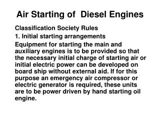
Air Starting of Diesel Engines. Classification Society Rules 1. Initial starting arrangements

E N D
Air Starting of Diesel Engines Classification Society Rules 1. Initial starting arrangements Equipment for starting the main and auxiliary engines is to be provided so that the necessary initial charge of starting air or initial electric power can be developed on board ship without external aid. If for this purpose an emergency air compressor or electric generator is required, these units are to be power driven by hand starting oil engine.
2. Air compressors • Two or more air compressors are to be fitted having a total capacity, together with a topping-up compressor where fitted, capable of charging the air receivers within 1 hour from atmospheric pressure, to the pressure sufficient for the number of starts required. The capacity of the main air compressors is to be approximately equally divided between them. The compressors are to be so designed that the temperature of the air discharged to the starting air receivers will not substantially exceed 93°C in service. A small fusible plug or an alarm device operating at 1210C is to be provided on each compressor to give warning of excessive air temperature. Each compressor is to be fitted with a safety valve so proportioned and adjusted that the accumulation with the outlet valve closed will not exceed 10 % of the maximum working pressure. The casings of the cooling water spaces are to be fitted with a safety valve or bursting disc so that ample relief will be provided in the event of the bursting of an air cooler tube.
3. Air receiver capacity • Where the main engine is arranged for air starting, at least two air receivers of approximately equal capacity are to be provided. The total air receiver capacity is to be sufficient to provide without replenishment, not less than 12 consecutive starts of the main engine, alternating between ahead and astern if of the reversible type. And not less than six consecutive starts if of the non-reversible type.
4. Draining of Air Bottles • The air discharge pipe from the compressors is to be led direct to the starting air receivers. Provision is to be made for intercepting and draining oil and water in the air discharge for which purpose a separator or filter is to be fitted in the discharge pipe between compressors and receivers. The starting air pipe system from receivers to main and auxiliary engines is to be entirely separate from the compressor discharge pipe system. Stop valves on the receivers are to permit slow opening to avoid sudden pressure rises in the piping system. Valve chests and fittings in the piping system are to be of ductile material. Drain valves for removing accumulations of oil and water are to be fitted on compressors, separators, filters and receivers.
Isolating non-return valve between air bottle and engine, Bursting disc or Flame arrestor • The starting air piping system is to be protected against the effects of explosions by providing an isolating non-return valve or equivalent at the starting air supply to each engine. In direct reversing engines bursting discs or flame arresters are to be fitted at the starting valves on each cylinder; in non-reversing and auxiliary engines at least one such device is to be fitted at the supply inlet to the starting air manifold on each engine. The fitting of bursting discs or flame arresters may be waived in engines where the cylinder bore does not exceed 230 mm.
Interlocks on starting • 1. Turning gear is disengaged : The turning gear acts as a lock to the engine, preventing it from turning during maintenance etc. Therefore cranking the engine with the T/G engaged will cause much damage to the T/G as well as the e n g i n e. • 2. Distributor position is as ordered and in end position: The starting air distributor cud position is checked to be in the right end position, as ordered at the telegraph before a start signal is forwarded. • 3. Main Lub Oil. pressure is present: A hydraulically -operated valve, sensing L.O. pressure blocks the start signal in absence of L.O. pressure. • 4. Air spring pressure is present: In engines with pneumatic closing of exhaust valves, the absence of this air spring pressure, causes a block of starting air signal. • 5. Aux blower running: In engines with constant pressure turbocharging, if the auxiliary blower is not started or has failed. the starting signal is blocked usually.
Checks for leaky start air valves, in port and at sea • In port • Ideally this has to be done unit by unit, taking each to TDC. Other wise a minor leak cannot be detected if the unit is at BDC. The steps involved are as follows: • Open indicator cocks • Engage turning gear • Take unit to TDC • Disengage turning gear • Shut off air to distributor • Pressurize main start air distribution pipe. • Check for air issuing out of indicator cock • Note: In the normal case the engine doesn’t turn on air since the air to distributor is shut. But in • case of a leaking start air valve the engine would turn. Hence the turning gear has to be disengaged before the distribution pipe is pressurized. • At sea • Feel for hot start air inlet branch pipes.
Actions in emergencies • Action in case of engine failing to start due to a sticking pilot or air start valve, during • Maneuvering: With a reversible main engine, the easiest step to follow is to request bridge for an kick in the other direction and get the engine out of the blind spot. Note that this is possible since if one unit start air valve or pilot is sticking and if that is the unit to receive start air in one direction. (that is when start fails), then on reversal of the engine. it will be definitely some other unit which is to receive start air for the other direction. • Action in case of bursting disc burst. • The bursting disc hood can be turned to temporarily regain maneuvering in case of a bursting disc burst.
Operation with cylinder out of operation • If the running gear is removed and the piston is hung , start air to the unit should be blanked as otherwise the hung piston will be forced down by start air pressure. Note that in such a case, the engine may not be fully maneuverable. A similar situation as mentioned above occurs, the remedy being the same as given above
Slow turning • Is an alternative to blow through. In bridge controlled ships, bridge may take considerable time to start engine even after handing over engine to bridge. Since F.O., L.O., and F. W. systems are running after handing over control to bridge. there is a chance of fluid accumulation in the unit if there is a leak of any of these fluids. To prevent a hydraulic lock from damaging the engine when starting with such a fluid accumulation in the unit. slow turning feature is provided. After a preset time on bridge control, usually 30 mts., the engine goes into slow turning mode automatically. The engine does not turn in this mode, only the indication will be on. When the engine is started from bridge when in this mode, the engine turns over slowly first for one complete revolution and then starts. Slow turning is accomplished by controlled admission of starting air. Slow turning can be initiated manually from E.C.R. and also cancelled from bridge.
Bridge control • Three repeated starts are usually carried out automatically in case of start failure at the first attempt. However the bridge start is blocked at low level of start air pressure which leaves sufficient air for the engineer attending, to start locally. On bridge controlled ships the start air from air bottles is to be always leftopen during sea passagealso.
Why start air admission before TDC? • In order to make maximum utilization of the entire start air period, it is essential that the unit is fully pressurized with full starting air pressure right at TDC. If the start air admission starts at TDC, due to mechanical delay, by the time unit is full pressurized and the air exerts a turning torque, the unit will be well past TDC, which represents a loss of starting air range. Hence the start air admission is slightly before TDC so that at TDC the unit it full pressurized to turn the engine. Admission of air before TDC does not turn the engine other way than the required direction due to the cylinder which is overlapping which exerts much greater turning torque in the required direction.
Why inverse cams are used as stating air cam? • Inverse cam is preferred as starting air cam since it provides the easiest arrangement of taking the rollers out of action once the engine has picked up on fuel. This will reduce wear and tear of air distributor valve when engine is running normally on fuel. Also, with the inverse cam arrangement, there is no possibility of mistimed admission of starting air in case of stuck pilot valves or broken spring.
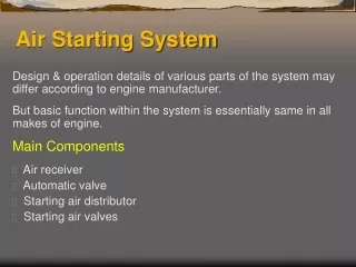
Air Starting system components • 1.Main or Automatic air start valve • 2. Air distributor • 3 . Start air valves on cylinder head.
Main or Automatic air start valve • This valve as the name suggests opens automatically during start and closes after the start. Isolation between engine and air bottle is the main purpose. • This valve may incorporate a non return valve to stop the flame front in case of a starting air line explosion. In some cases, the non return valve may be a separate component. The automatic valve is also used for blocking an engine start or putting into service. Provision for manual opening can also be provided. Slow turning device, if fitted, is incorporated in the automatic valve. Latest B & W design of automatic valve is a simple ball valve actuated by a piston through a rack.
Air distributor • The air distributor may be basically of two kinds, the rotary type, and the pilot valve and inverse cam type. The rotary distributor designs are common in generators and also is used in some main engines too. The pilot valves may be mounted separately and the inverse cams also separately mounted on the main camshaft next to each unit instead of grouping them together as a distributor. This arrangement is found in reversible four stroke engines. The pilot valve along with the inverse cam is termed the distributor which controls the timing of air admission for a particular unit. Pilot valves are also prone to getting stuck and hence of non corrodible material
Start air distributor B & W engine • The pilot valve is a spool type valve held up by spring pressure during normal running of the engine. The other end of the spool valve bears on an inverse cam when operating air at 30 bar (or starting air pressure) is admitted into the space below piston 1. This pressure acts on the top of piston 2 and also on bottom of piston 1. The top of piston 2 area being larger. the resultant force is to keep the pilot valve spool pressed onto the inverse cam against the spring pressure. If the inverse cam position allows, the pilot spool further moves down. This movement does the following.
1. The operating air inlet is cut off by the piston 1 covering the hole though which operating air was admitted, which traps the 30 bar operating air pressure in the space between piston 1 & 2. This means that even if the external operating air line is vented, the trapped air keeps the pilot valve at the activated position till the inverse cam mechanically pushes it back. This is the arrangement that ensures that those units in the starting air range. at the instant of changing over form air start to fuel run, continues receiving starting air though external operating air is vented. • 2. The line to start air valve which is vented is connected to the pilot air line, This is by the piston 3 covering the vent and at the same time allowing air into the start air valve line. • During normal running, the pilot valve is kept off the cam preventing unnecessary wear. • There are as many pilot valves as the number of units. Reversal of start air distributor is by shifting the shaft axially by a pneumatic cylinder.
Start air valves on cylinder head. • The starting air valve in cylinder head of each unit admits air into the cylinder during starting. • Pneumatically operated start air valves are used and the start air valve designed such that if the unit is firing, the combustion pressure prevents the start air valve form opening even if the pneumatic pressure for opening is present from the distributor.
With pneumatic operation of start air valve, the application of pilot air to start air valve does not necessarily mean the valve opens, but depends on the pressure in the cylinder. This has reduced of chance of starting air line explosion greatly. The valve piston and liner etc are of non corrodible material, so that moisture content in the pilot air does not cause corrosion and eventually jamming of valve. Grease points are provided outside for lubrication. Flats or screw driver slots on top of valve spindle enables checking of valve freeness. SULZER design has both opening and closing pilot air; whereas B & W uses only opening air, closing is done by spring force (figure shown here).
Reversing of a Diesel Engine • Reversed running of a diesel engine can best be understood by considering individually the four processes given below that takes place during engine operation. • Inlet, • Exhaust. • Starting air admission, • Fuel injection.
These four processes are timed in relation to power piston movement, which gives their timings. • The timings are given in relation to any Dead Center, TDC or BDC, as “X” degrees before Dead center to “Y” degrees after Dead Center. Each of the four individual processes mentioned above are controlled by cams. Each one may or may not need repositioning for reversed running of the engine. Whether reversal arrangement in needed for a particular process depends on the disposition of the total cam angle about roller contact point on the cam, when the unit in question is at dead center. If a certain process commences “X” degrees before dead centre and terminates “X” degrees after dead centre (symmetric timing), then there is no need for a reversal arrangement. Therefore for the first three processes, reversal arrangement is needed when the timing is asymmetric.
Methods of repositioning timings for engine reversal, can be broadly classed into following two types. • 1 . Using same cam for ahead and astern running. • 2 . Using a different set of astern cams for astern running, by shifting the cam shaft axially.
Using same cam for ahead and astern • When the same cam is used for ahead and astern running, it means that the angular relation between the crank shaft and cam has to change or the point at which the roller is activated has to be shifted. This angular relation change can be achieved by any of the following methods. • By turning the cam shaft (along with the cams mounted on it) through the required angle in the required direction keeping the crank shaft stationary. • By turning the cams alone on the cam shaft. • The point of actuation of the roller can be changed by shifting the roller transverse to the engine.
Using a different set of astern cams • In this case the cam shaft is shifted axially to bring into play a different set of astern cams. In four stroke engines this is the only method used. Using a different sets of ahead and astern cams means that the cam shaft has to be axially shifted for reversal. In order to achieve this, the cams have a gradual flow from one to the other so that the roller cam smoothly move from one cam to the other.