Download
1 / 5
50 likes | 153 Vues
ECS meeting – May 2009 - Clermont team. PRS VFE temperatures Architecture. Measurements. DCS-related actions. Disclaimer: my personal view as input for the discussion. DCS SUPERVISOR PC’s CADCS02W. VFE TEMP. CONTROL. HV MONITORING. POWER SUPPLIES CONTROL. ELMB’s. HV PROJECT.

E N D
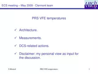
ECS meeting – May 2009 - Clermont team PRS VFE temperatures • Architecture. • Measurements. • DCS-related actions. • Disclaimer: my personal view as input for the discussion. PRS VFE temperatures
DCS SUPERVISOR PC’s CADCS02W VFE TEMP. CONTROL HV MONITORING POWER SUPPLIES CONTROL ELMB’s HV PROJECT RACK CONTROL PROJECT REG. TUBES ECS meeting – May 2009 - Clermont team 1) DCS Architecture. Anatoli’s talk This talk PRS VFE temperatures
ECS meeting – May 2009 - Clermont team 2) Measurements collected in temperature project. • PVSS project developed by Maxim Martemianov, further handled by Jean-Luc Panazol (thanks!). • 2 temperature probes on a single VFE. • 2 temperature probes on a single regulator. • Project was extremely useful to diagnose cooling weaknesses in the past. • Robust. PRS VFE temperatures
ECS meeting – May 2009 - Clermont team 3) Alarm, actions, states and so on … • We can set an alarm threshold on each of the measurement. Individual alarms can be obtained such as : get measurements when cooling will be back and stable. Distribute it and fit the mean value <T(i)>+ and spread s: TTHR(i)=[<T(i)>+n.s]°C. • Use cases and actions: The only DCS action which can be taken: stop the LV VFE per side (50 boards in a whole). Nota Bene 1: the increase of temperature yields an increase of the channel pedestal. In normal data taking, it shall be first seen by the pedestal monitoring. Nota Bene 2 : so far, we «only» experienced general cooling problems. Try in the following to envisage more. PRS VFE temperatures
ECS meeting – May 2009 - Clermont team 3) Alarm, actions, states and so on … • One temperature above threshold : send an alarm (WARNING state). no DCS action redefine accordingly the alarm threshold. • The two probes on the same board yield alarms. This is real. ERROR state. Might be a chip over-consumption or a localized cooling problem. No DCS action (but DAQ and trigger actions - modify FE state ?) redefine accordingly the alarm threshold. Data quality warning ? • Several probes yield alarms. FATAL state. This is a true cooling problem. DCS action DCS cuts the VFE. PRS VFE temperatures