Progress on Solid Target Studies J. R. J. Bennett
180 likes | 345 Vues
Progress on Solid Target Studies J. R. J. Bennett Rutherford Appleton Laboratory, Chilton, Didcot, Oxon, OX11 0QX 2 nd Oxford-Princeton High-Power Target Workshop, 6-7 November 2008, Princeton.

Progress on Solid Target Studies J. R. J. Bennett
E N D
Presentation Transcript
Progress on Solid Target Studies J. R. J. Bennett Rutherford Appleton Laboratory, Chilton, Didcot, Oxon, OX11 0QX 2nd Oxford-Princeton High-Power Target Workshop, 6-7 November 2008, Princeton
(J. R. J. Bennett1), G. Skoro2,J. Back3,S. Brooks1, R. Brownsword1, C. J. Densham1, T. R. Davenne1, R. Edgecock1, S. Gray1, P. Loveridge1 and A. J. McFarland1 1 Rutherford Appleton Laboratory, Chilton, Didcot, Oxon. OX11 0QX, UK 2 Department of Physics and Astronomy, University of Sheffield, Sheffield. S3 7RH, UK 3 Department of Physics, University of Warwick, Coventry. CV4 7AL, UK
Outline 1. Reminder of the Solid Target Design and Studies. 2. Progress on measuring target lifetime. 3. Progress on measuring shock motion using the VISAR. 4. Future work.
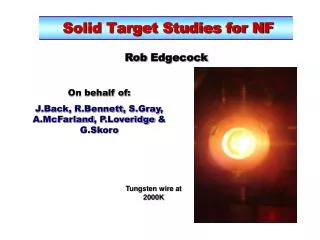
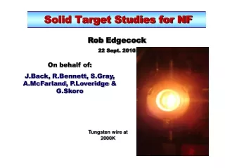
Solid Target Studies • The original idea was to have a tantalum toroid rotate through the beam and threading the pion collection/focussing solenoid. The toroid operated at ~1600 K and radiated the heat to the surrounding water cooled walls. • The main problem was considered to be thermal shock generated by the ns long proton pulses (10 GeV, 4 MW beam). • Thermal Shock Studies: A) Lifetime Test. • A high current pulse was passed through a 0.5 mm diameter tantalum wire, simulating the stress expected in a full size target. The number of pulses was counted before failure of the wire. Tantalum quickly proved to be too weak and was replaced by tungsten . Great care was needed to align the wire in the support structure to minimise the very large Lorenz magnetic forces. Most failures were probably due to this and to the wire sticking in the sliding free-end support /electrical connection.
It soon became evident in the wire shock tests that thermal shock was not the problem. The wire was not failing from a single or a few shock pulses, but could survive millions of pulses. The problem is not thermal shock but fatigue and creep. Fatigue and creep are not amenable to analysis. It is not possible to predict the number of cycles to failure with any accuracy.
Vertical Section through the Wire Test Apparatus Spring clips Sliding connection Two graphite (copper) wedges Current Tungsten wire Stainless steel split sphere Fixed connection Copper “nut” Inner conductor of co-axial insulator feed-through. Current
W26 Tungsten Wire Assembly
Some Results: 0.5 mm diameter Tungsten Wires “Equivalent Target”: This shows the equivalent beam power (MW) and target radius (cm) in a real target for the same stress in the test wire. Assumes a parabolic beam distribution and 3 micro-pulses per macro-pulse of 20 micro-s.
Conclusions I believe that the viability of solid tungsten targets at high-temperaturefor a long life (~10 years) has been demonstrated with respect to thermal shock and fatigue and will not suffer undue radiation damage.
3. Thermal Shock Studies: B) Measure Surface Motion and deduce the constitutive equations of state at high temperature under shock conditions. Currently a VISAR* is being used to measure the surface accelerations/velocities. We started by trying to measure the radial vibrations of the wire but once I understood how the VISAR worked it was clear that the expected signal would be in the noise. I am now setting up to measure the vibrations of the “free” end of the wire. This gives larger signals and should enable us to get results - when the power supply has been refurbished. *Velocity Interferometer System for Any Reflector
VISAR signals from the radial motion of a 0.5 mm diameter tungsten wire. (Calculated for simple sinusoidal oscillation of surface.) Signals in the noise.
Looking at the end of the wire will have other advantages: • Measuring the radial motions with the VISAR, it was not possible to have successive current pulse close together and hence to have the wire hot (~1800 K) because the wire bent and the laser (VISAR) was no longer aligned on the wire. Hence we could only carry out measurements at ~room temperature. • Measuring the axial motion, the “free end of the wire is well located (except axially) so heating the wire with successive pulses should not be a problem. Hence, we can make VISAR measurements from room temperature to (~1800 K).
Goran Skoro Measuring the free end of a 0.5 mm diameter tungsten wire. 6000 A pulse. 300 K 1500 K
Goran Skoro Measuring the free end of a 0.1 mm diameter tungsten wire. 1000 A pulse. 300 K Excessive Stress σ = 500 Mpa, ΔT = 500 K
The present power supply has a 100 ns rise time and 800 ns flat top. Ideally we would like a faster shorter pulse to generate the shock. A prototype capacitor/spark gap power supply has been built and tested to give shorter pulses – 20-30 ns rise and 30-40 ns fall, no flat top, peak current 20-40 kA. Measuring the end motion of the wire and using this capacitor power supply and the original psu will enable us to obtain good VISAR signals for wire temperatures from 300 to 1800 K and simulate the stresses to be found in the target. Calculations using LS-DYNA by Goran Skoro to simulate the shock stress and motions in the target and wire. Also simulating the VISAR signals.
Current and Future Work • Complete VISAR measurements (longitudinal motions of the test wire). Build (probably) capacitor psu? • Continue life tests on wires. • Life and radiation tests of better materials – WReHfC? • In-beam few pulse test of a W bar on ISIS. • Continue to study pion yield and capture and the solenoid field requirements. • Mechanical design of the target bar moving mechanism and the solenoid. Once we have a really nice solution to moving the bars in and out of the beam the target problem is solved since we have shown that the lifetime is >10 yrs (– but should have in-beam test). • Target station design and costing.