Accurate Physical Model for Lateral IGBT in Silicon On Insulator Technology
310 likes | 414 Vues
Develops a precise physical circuit model for lateral IGBT in SOI tech, crucial for smart power design. With detailed behaviors & numerical results.

Accurate Physical Model for Lateral IGBT in Silicon On Insulator Technology
E N D
Presentation Transcript
Accurate Physical Model for the Lateral IGBT in Silicon On Insulator Technology Ettore Napoli1,2, Vasantha Pathirana1, Florin Udrea1,3 1 Dept. of Engineering, University of Cambridge, UK 2 Dept. Electronic and Telecom. Univ. of Napoli, Italy 3 Cambridge Semiconductor (CamSemi), UK EU research program ROBUSPIC ISIE, Dubrovnik, June 21st 2005
Outline • Motivation • Thin SOI LIGBT • Differences with Vertical IGBT • Spice sub-circuit model for LIGBT • Model equations • Model behavior • Numerical results • Conclusion ISIE, Dubrovnik, June 21st 2005
Motivation • Available IGBT circuit models are not suited to Lateral IGBT • Need for • a reliable physical based model for Lateral IGBT • usable in various circuit simulators • Extension to different LIGBT technologies • Important for smart power design ISIE, Dubrovnik, June 21st 2005
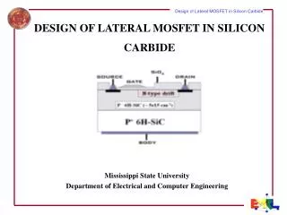
Thin SOI Lateral IGBT • 600V PT • Transparent buffer • Source and Drain up to the BOX • Current flow is horizontal and 1D ISIE, Dubrovnik, June 21st 2005
Differences with Vertical IGBT (1) • Not zero carrier concentration at the collector edge for LIGBT ISIE, Dubrovnik, June 21st 2005
Differences with Vertical IGBT (2) • Electrons injected from the n+ accumulation layer into the n- drift across the n+/n- junction. • The structure features double injection (similar to a PIN or a thyristor) ISIE, Dubrovnik, June 21st 2005
Differences with Vertical IGBT (3) • Total charge and charge profile LIGBT Vertical IGBT ISIE, Dubrovnik, June 21st 2005
Differences with Vertical IGBT (4) • Depletion width vs. reverse voltage is influenced by 2D effects ISIE, Dubrovnik, June 21st 2005
Differences with Vertical IGBT (5) • Depletion width LIGBT vs. Vertical IGBT • 0V ISIE, Dubrovnik, June 21st 2005
Differences with Vertical IGBT (5) • Depletion width LIGBT vs. Vertical IGBT • 5V ISIE, Dubrovnik, June 21st 2005
Differences with Vertical IGBT (5) • Depletion width LIGBT vs. Vertical IGBT • 10V ISIE, Dubrovnik, June 21st 2005
Differences with Vertical IGBT (5) • Depletion width LIGBT vs. Vertical IGBT • 100V ISIE, Dubrovnik, June 21st 2005
Differences with Vertical IGBT (5) • Depletion width LIGBT vs. Vertical IGBT • 200V ISIE, Dubrovnik, June 21st 2005
Differences with Vertical IGBT (5) • Depletion width LIGBT vs. Vertical IGBT • 300V ISIE, Dubrovnik, June 21st 2005
Differences with Vertical IGBT (6) • Depletion region mobile charge effect ISIE, Dubrovnik, June 21st 2005
IGBT models not suited for LIGBT • Voltage rise at turn-off is faster due to lower charge in the epilayer and slower depletion width expansion ISIE, Dubrovnik, June 21st 2005
Spice sub-circuit model for LIGBT Currents and voltages Epilayer charge equation ISIE, Dubrovnik, June 21st 2005
Spice sub-circuit model for LIGBT • Vj : Emitter junction • Vdrift: Depends on the injected carriers • analytic solution • Vmos: Mosfet (level 1) ISIE, Dubrovnik, June 21st 2005
Spice sub-circuit model for LIGBT • IN(W) : Electron current through the level 1 Mosfet ISIE, Dubrovnik, June 21st 2005
Spice sub-circuit model for LIGBT • IP(W) : Bipolar hole current ISIE, Dubrovnik, June 21st 2005
Spice sub-circuit model for LIGBT • IN(0) : Electron current through the emitter junction ISIE, Dubrovnik, June 21st 2005
Spice sub-circuit model for LIGBT P0 Time is increasing PW Wt Wt+δt Wt+2δt 0 Increasing Anode Voltage Stable Anode Voltage • IPC_TRN : Transient current due to charge sweep-out ISIE, Dubrovnik, June 21st 2005
Base charge equation • IN(W) is the MOSFET current • IN(0) is the emitter edge electron current • IPC_TRN is the charge sweep out current • The last term is for the recombination in the base ISIE, Dubrovnik, June 21st 2005
Other model features • Carrier concentration dependent mobility model • Gate-Source Drain-Source and Gate-Drain capacitances are implemented • Physical based model with 17 parameters ISIE, Dubrovnik, June 21st 2005
Spice circuit parameters ISIE, Dubrovnik, June 21st 2005
Static characteristics ISIE, Dubrovnik, June 21st 2005
Model behavior Expanded for I=1A, V=200V InductiveTurn-off ISIE, Dubrovnik, June 21st 2005
Transient behavior V=200V, I=2A. V=400V, I=2A. ISIE, Dubrovnik, June 21st 2005
Transient behavior Resistive switch, 200W resistor load ISIE, Dubrovnik, June 21st 2005
Model behavior Toff Energy vs. Von as a function of lifetime ISIE, Dubrovnik, June 21st 2005
Conclusion • A physical based circuit model for Lateral IGBT • Implemented in Spice • Defined through 17 physical parameters • Compared against device numerical simulation • Extendable to Thick SOI and JI-LIGBT ISIE, Dubrovnik, June 21st 2005