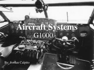
Aircraft Communication Systems (Introduction)
Aircraft Communication Systems (Introduction). DGCA: ATA-23 Presented by Arnav Mukhopadhyay URL : http:// gudduarnav.com/. TOPICS. Basic Principle of Radio Communication Frequency Allocation Chart for Aviation Radio Wave Propagation Antenna, Transmission Line, Wave guide. Avionics.

Aircraft Communication Systems (Introduction)
E N D
Presentation Transcript
Aircraft CommunicationSystems(Introduction) DGCA: ATA-23 Presented by Arnav Mukhopadhyay URL:http://gudduarnav.com/
TOPICS • Basic Principle of Radio Communication • Frequency Allocation Chart for Aviation • Radio Wave Propagation • Antenna, Transmission Line, Wave guide
Avionics • Branch of technology dealing with design, production, installation, use and servicing of electronics systems used on aircraft, artificial satellite and spacecraft • Avionics ◄◄ Aviation-Electronics
Avionics systems • Communication Systems : Keep interaction between Ground and Flight deck intact • Navigation Systems : Allows Aircraft to keep itself aware of its position in air space • Monitoring Systems: Keep Pilot informed through Glass Screen along with automating the flight process • Aircraft Flight Control Systems: Strictly tested software responsible for flight process automation • Collision avoidance system: Keeps aircraft away from objects that cause the plane to crash • Weather Systems: Keeps aircraft at safe distance from weather related disturbances and lightning strike • Aircraft Management Systems: All aircraft systems are centrally integrated with Aircraft Computer to inform maintenance team with early warning about any future failure of instruments/parts
Electromagnetic Waves • Wave that propagates by simultaneous periodic variations of Electric and Magnetic Field Intensity • Types: Radio Waves, Infrared, Visible Light, Ultraviolet Rays, X-rays, Gamma Rays
Quantifying EM Wave • Electromagnetic wave can be quantified using the following 4 properties: • Amplitude • Frequency (or Wavelength) • Phase • Polarization
Frequency Period = 0.5 sec Period = 1 sec • Period = Time duration after which the pattern of a periodic wave repeats • Frequency = = Number of times a wave pattern repeats within 1 second time
Wavelength • Wavelength = Distance between two CREST = Distance between two TROUGH
Communication System Communication Channel Receiver / Demodulator Transmitter / Modulator Baseband Signal Baseband Signal • Used to communicate / relay information from one point to another • Allows multiple signal to be multiplexed and sent over same channel (channel reusability) • Additional methods of protection can be applied so as to prevent unauthorized access to information • Safeguard information against channel related distortion
Baseband Signal • Low Frequency like Audio, Video, Digital Pulses • Faces high attenuation when transmitted over long distance • Interferes and mixes with each other when transmitted together Music (Audio) Signal CW (Morse Code) Signal TV Video Signal
Modulation • Changing a property of Carrier EM wave according to the baseband signal • Modulation or Carrier Frequency >> Base band signal Bandwidth • Modulated signal experiences limitations faced by Carrier/EM wave, but become free from limitations faced by the baseband signal • Allows multiple modulated signals to be carried through the same channel without interfering with each other • Allows communication of signals over a long distance • Wireless (Air Interface) communication can be used (called Radio Communication) FM Radio Spectrum GPS Signal Spectrum
Types of Modulation Digital Modulation Analog Modulation Pulse Modulation Data Modulation Angle Modulation Amplitude Modulation • PAM (Pulse Amplitude Modulation) • PPM (Pulse Position Modulation) • PWM (Pulse Width Modulation) • PCM (Pulse Code Modulation) • ASK (Amplitude Shift Keying) • PSK (Phase Shift Keying) • FSK (Frequency Shift Keying) • QPSK, MSK, … Frequency Modulation Phase Modulation
Amplitude Modulation • Amplitude of Carrier wave is changed according to the amplitude of baseband signal • Depth of Modulation is the ratio of the Amplitude of Baseband signal to the Amplitude of Carrier Wave • Modulator and Demodulator are easy to implement and cheap • Inefficient in terms of Bandwidth and Power usage • AM signals are prone to high levels of noise • Used in Aviation Voice Communication Audio Signal AM Modulated Signal AM Modulated Spectrum
Phase Modulation • Instantaneous Phase of Carrier Wave is varied proportionally to the Instantaneous amplitude of the Baseband Signal • Phase modulation & demodulation is easier to attain compared to Frequency Modulation • Phase Ambiguity during demodulation may arise when the Phase Shift exceeds 180 degrees • Multipliers are required to increase Phase Modulation Index • Bandwidth is given by Carson’s Rule • Occupied bandwidth is nearly equal to the Bandwidth utilized for corresponding FM signal Audio Signal PM Modulated Signal PM Modulated Spectrum
Frequency Modulation • Carrier frequency is varied according to the amplitude of the baseband signal • Effect of Noise is minimum on the FM modulated waveform, makes it popular for commercial broadcast radio • Received FM Signal strength variation does not affect the demodulated signal amplitude • FM modulation is achieved using nonlinear amplifier, which makes it more efficient in terms of spectrum utilization • FM demodulator circuits are more complex • Practical FM Bandwidth is Infinity. Theoritical, Bandwidth is given by Carson’s Rule: Audio Signal FM Modulated Signal FM Modulated Spectrum
TOPICS • Basic Principle of Radio Communication • Frequency Allocation Chart for Aviation • Radio Wave Propagation • Antenna, Transmission Line, Wave guide
TOPICS • Basic Principle of Radio Communication • Frequency Allocation Chart for Aviation • Radio Wave Propagation • Antenna, Transmission Line, Wave guide
Radio Wave Propagation Types of Radio Wave Propagation Tropospheric Propagation Ionospheric (Sky wave) Propagation Free Space Propagation Ground Wave Propagation Propagation using Sporadic E Meteor Scatter Communications Trans-Equatorial Propagation (TEP) Near Vertical Incidence Skywave (NVIS) Propagation using Auroral Backscatter Propagation using Moon Bounce Effect (Earth-Moon-Earth)
Ground Wave Propagation • Ground wave = Direct Wave + Reflected Wave + Surface Wave • Used for relatively local radio transmission • Used for day time communication, when Ionospheric communication is not possible • Band used: • LF (30-300 KHz) • MF (300-3000 KHz) • Antenna used: Ferrite Rod based Magnetic Field antennas
Surface Wave Propagation • Follows curvature of the earth and traces the ground surface • Direct Ray decays after line of sight and extended range is covered by Surface Wave • HF (3 MHz) wave faces 20-60 dB more attenuation than 0.5 MHz • Attenuation of Surface wave increases with increase in frequency • Surface Wave attenuation depends on ground topology (affects attenuation and scattering), presence of sea water (saline water provides reduces attenuation), sand (increases attenuation), vertical polarization (less attenuated) preferred.
Ionosphere (Sky Wave) Wave Propagation • Ionosphere acts as reflector and make long-distance communication possible • 3-30 MHz frequency bands are reflected • Strongly influenced by sunspot number, geomagnetic storms, daytime Ionospheric disturbances • During night time, Ionospheric Ionization Density falls due to reduced solar activity, which increases the virtual height
Tropospheric Propagation • VHF or UHF transmission (line of sight transmission) can be received beyond the horizon • Troposphere condition can bend the waves in these bands using higher refractive index exhibit due to the atmospheric conditions • Atmospheric conditions: Fog (during morning near sun rise), weather (high pressure systems), Inversion of Temperature Gradient (Vertically downward flowing cool air systems) • Signal intensity rapidly weakens and signals are shadowed by noise • Can lead to interference with the local signal
Free Space (Line of Sight) Propagation • Frequency above 30 MHz cannot be reflected back by ionosphere and ground wave or sky wave attenuation rapidly weakens the signal • FSP (Free Space Propagation) via Direct Line of Sight and Ground Reflection are only possible way to relay the signal • Service of these wave beyond Line of Sight is delivered by space based Satellite • FSPL (Free Space Path Loss) increase with increase in Frequency • Atmospheric absorption and scattering are observable at Microwave Frequencies
TOPICS • Basic Principle of Radio Communication • Frequency Allocation Chart for Aviation • Radio Wave Propagation • Transmission Line, Wave guide, Antenna
Transmission Line • A specialized cable or structure to convey Radio Waves to the destination • Examples: • Two-conductor transmission line • Parallel Line (Ladder Line) • Coaxial Cable • Stripline • Microstrip • Waveguide Open Wire (Ladder) Line Microstrip Strip Line
Coaxial Cable • Electrical cable with two conducting cylindrical wire separated by dielectric medium • Used to carry high frequency electrical signals with low attenuation • The maximum value of frequency that can propagate through Coax is: • Used to connect Antenna to Radio Receiver and Transmitter Devices, Broadband Internet, Cable TV connection, Telephone Trunk line
Wave guide • Structures that guide waves especially at microwave and mmW domain • Capable of handling high power, but they are costly and bulky at low frequencies • Operation Frequency: 1 – 220 GHz • Classification: • Rectangular waveguide: Hollow rectangular enclosure with metal used for enclosure (looks like rectangular metal pipe) • Circular waveguide: Cylindrical metal enclosure • Application area: High Power Radio Systems like RADAR, Satellite systems and some precision test systems Rectangular Waveguide (7/8”x5/8”) Circular Waveguide
Antenna • A device which acts as an interface between the Electric Current in metallic conductor and the radio waves in free space. An important component of Radio Communication System • Antenna which radiates radio wave uniformly and equally in all direction is called Isotropic Radiator (or Antenna. It is an ideal antenna • Other antennas: Monopole Antenna, Dipole Antenna, Parabolic Reflectors, Horn Antenna • Antenna exhibits Gain, which determines the amount of power radiated relative to the power imparted. The higher the Antenna Gain more will be the radiated power. • High gain antenna are more directed, because they emit Radio Wave in Narrow Beam Circuit Symbol Half-Wave Dipole Antenna Antenna Radiation Pattern
EM Interference • Aircraft Radio systems are very susceptible to interference from various sources • Interference can be caused by radiation or conduction • Static Build up due to Atmosphere (Radiated RF Noise): • Aircraft flying through cloud formations, picks up charge • Uneven charge build up leads to strong Electric Field on the Aircraft’s Body • Strong Electric Field leads to unwanted sparking • Sparking appears as sudden increase in Wide Band RF Noise spectrum • This cause wanted Signal to be masked momentarily (by decrease of SNR) • Prevention: Prevent charge build up by connecting a very low resistance metallic strap between all aircraft equipment
EM Interference • Discharge between Aircraft and Atmosphere • Occurs when large potential difference appears between Aircraft and Atmosphere, which cannot be avoided • This discharge should be kept away from Antennas • PREVENTION: Static Discharge (High Resistance, Low Corona Voltage material) are fitted to trailing edge of the main plane, tail plane, vertical stabilizer • Fit many static discharge to keep the potential difference low to prevent discharge • Bonding material should be capable of handling high discharge current • Lightning conductor are fitted on Nose • Wire antenna will have high resistance path between itself and airframe to allow static charge leakage
EM Interference • Spark pickups from DC motors, generators, engines • PREVENTION: Provide low resistance RF path between Commutators, Brushes, Contacts using Capacitor. Process is known as Suppression. • Capacitive and Inductive Pickup from Adjacent Cables • Interference from nearby 400 Hz Aircraft power line • Pickup of signals from nearby RF communication cables • PREVENTION: Twisted Pair cable are used to reduce pickups. Earthed (Shielded) cable will remove the low frequency inductive pickups. Radio Altimeter uses Double Shielded cable • Magnetic field associated interference with Electronics • PREVENTION: Keep susceptible instruments away from magnetic instruments like compass • Affected devices are generally marked with “Compass Safe” Distance. These details must be cared for • Also check cables and DC power lines
EM Interference • Mutual Interference due to Antenna Placement • PREVENTION: Keep antennas within same band adequately separated • Frequency and Time Domain must be used to prevent interference • Using Polarization Diversity (Signals are separated using Polarization) will reduce cross-coupling of signals between antennas • Use Narrow Band Receiver to reduce the capture of adjacent band signal • Using proper IF Frequency, and high Q IF Amplifiers in Super-heterodyne Receivers • Increase inter-channel guard band size
Maintenance • Follow standard checks as applicable. Additionally special checks as per Manufacturer specifications must be separately done • BITE (Built-in Test Equipment): Modern equipment offers automatic test and monitoring facilities which offers comprehensive check of the system. Test result from BITE must be considered to certify the serviceability of the system
Installation/Maintenance Checks • Weight of Units to avoid problem with centre of gravity • Current drawn should not exceed Circuit Breaker requirements • Cooling methods used to prevent Equipment failure due to Overheating • Mounting mechanism: Anti-vibration mount for metallic systems. For non-metallic systems, bonding straps may be required • Cable length and types, so that it can withstand the current drawn • Antenna positions, types and specifications as required by particular aircraft • Interfacing methods: Impedance matching between two devices. Pin matching between connectors • Compass safe distance to prevent magnetic field interference • Radiation hazards
Organizations, Conference related to Aircraft Radio Systems
References • D. Crane, “Airframe Volume 2: Systems”, Aviation Maintenance Series, Aviation Supplies & Academics Inc. (2nd Edition, 1999), Chapter-11 • J. Powell, “Aircraft Radio Systems”, Himalayan Publishers (2009) (ISBN: 81-7002-091-3) • I. Angulo, Les Barclay, Y. Chernov, N. Deminco, I. Fernandez, U. Gil, D. Guerra, J. Milsom, I. Pena, D. De La Vega, “Handbook on Ground Wave Propagation”, Radio communication Bureau (2014 Edition) • S.K. Mitra, “The Upper Atmosphere”, the Asiatic Society (Monograph Series Vol. V) (1992) • D. M. Pozar, “Microwave Engineering”, Wiley Pub. (4th Ed) (2013) (ISBN: 978-81-265-4190-4)