Download
1 / 17
170 likes | 291 Vues
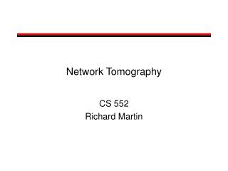
Network Tomography based Unresponsive Flow Detection and Control. Authors Ahsan Habib, Bharat Bhragava habib,bb@cs.purdue.edu Presenter Mohamed M. Hefeeda Department of Computer Sciences Purdue University Support: NSF, CERIAS, IBM. Motivation.

E N D
Network Tomography based Unresponsive Flow Detection and Control Authors Ahsan Habib, Bharat Bhragava habib,bb@cs.purdue.edu Presenter Mohamed M. Hefeeda Department of Computer Sciences Purdue University Support: NSF, CERIAS, IBM FTDCS 2003
Motivation • Efficient resource management by utilizing wasted resources • Adaptive flows do not starve due to unresponsive flows • Coordinated congestion control by propagating congestion information to upstream domains
Example • Unresponsive flows waste resources by taking their share of the upstream links and dropping packets at downstream links are congested
Related Work • Congestion collapse from undelivered packets[Flyod et al., TON ’99] • Network Border Patrol[Albuquerque et al., INFOCOM ’00] • Edge routers periodically poll cores[Chow et al., Internet draft ’00] • Direct Congestion Control Scheme[Wu et al., Internet draft ’00] • Loss of highclass packet means congestion • Core-assisted Congestion Control[Habib, Bhargava PDCS ’01]
Network Tomography • Network tomography uses correlations among end-to-end measurements to infer per-link characteristics. • Back-to-back packets experience similar congestion in a queue with a high probability [Duffield et al., INFOCOM ’01] • Receiver observes the probes and correlates them for loss inference • For general tree? Send stripe from root to every order-pair of leaves
Tomography-based Congestion Control (TCC) Only edge to edge measurements are used to detect and control unresponsive flows
TCC- Detection 1. Measure Delay • Ingress routers sample user traffic • The user packet headers are copied to probe edge-to-edge path for delay • Exponential moving weighting average is computed with more weight to the recent history and less weight to the current sample • If probed delay is higher than a specified threshold, a path is suspected to be congested
TCC- Detection (Cont’d) 2. Measure Loss • A loss probing tree is generated with a set of paths that have high delay. • The tree is probed to infer loss ratio of each individual link of the suspected paths • Need to know • Topology • Senders • Receivers
TCC- Detection (Cont’d) 3. Identify egress routers • Through which suspected flows are leaving the domain. The links with high losses are feeding flows to these routers 4. Identify misbehaving flows • These are determined with the rate at which suspected flows are entering into and leaving from a domain
TCC- Control • We know the misbehaving flows from detection • The rate of suspected flows are adjusted based on • Loss ratio and • Change of loss ratio with time
Experiments: Evaluation methodology • Simulation using ns-2 • Use parameter settings (queue, traffic, …) from reference work • Input Parameters • We vary RTT, number of flows, and life time of flows • Output Parameters • Measure delay, loss ratio, throughput Topology
Delay Measurements • End-to-end delay is high due to excessive flows • With control the delay goes down End –to-End Delay (Sec) Time (Sec)
Loss inference Validation • Three different experiments • Actual loss is close to infer loss • Converges within 10-15 sec Inferred Loss Actual Loss
Flow Control Bandwidth (Mbps) TCP congestion window Time (Sec) Time (Sec) Flow control mechanism increases the bandwidth of adaptive flows by consuming bandwidth wasted by unresponsive flows
Flow Control • Loss ratio of an unresponsive flows with and without flow control • Goes down sharply with time • Converges to a low specified value Loss Ratio Time (Sec)
Flow Aggregation… • 6-10 aggregate flows of each type • 10-100 micro flows per aggregate • Works fine even more and more flows misbehave Bandwidth (Mbps) Number of flows
Conclusion • A new way to detect and control unresponsive flows • No involvement of core routers • Scalable • Easy to deploy • Low overhead. Probe traffic less than 0.015% of the link capacity (OC3)