Download
1 / 25
250 likes | 435 Vues
BAY-LOGI. 1st Hungarian-Ukrainian Joint Conference on SAFETY-RELIABILITY AND RISK OF ENGINEERING PLANTS AND COMPONENTS”. Integrity Assessment of Dissimilar Metal Weld s. Szabolcs Szávai Dr. Gyöngyvér B. Lenkey. EU5 ADIMEW proje c t ’s objectives.

E N D
BAY-LOGI 1st Hungarian-Ukrainian Joint Conference on SAFETY-RELIABILITY AND RISK OF ENGINEERING PLANTS AND COMPONENTS” Integrity Assessment of Dissimilar Metal Welds SzabolcsSzávai Dr. Gyöngyvér B. Lenkey
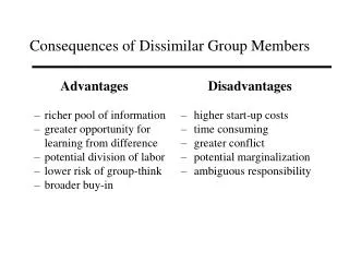
EU5 ADIMEW project’s objectives • Evaluation of conservatism and accuracy of structural integrity assessment methods applied in the European nuclear industry • Study of the behaviour of circumferential surface defect in a dissimilar metal weld • Perform a unique four point bending test of a real size welded structure with crack like defect with normal operation condition
BAY-LOGI acitivities in the project • Analysis of the effect of notch radius and its position in the buttering on the structural behaviors • Study the effect of the notch radius on fracture toughness • Study the effect of the defect distance from the fusion line on fracture toughness • Post test modelling of a real size mock-up with crack like defect in the dissimilar weld
Fracture toughness determination CT25 T=300 °C
Conclusions from the test results • The lower toughness value was obtained when the defect was closer to the fusion line (appr. 130 kN/m) • When the defect was farther from the fusion line, the toughness increased significantly(appr. 290 kN/m) • For sharper defect the toughness was lower (appr. 240 kN/m)
FE analysis on CT specimen with DMW • To study: • the effect of defect tip radius • the effect of the distance of the defect from the fusion line • the effect of material properties • comparison of notched and pre-cracked specimens
19 s mm Æ 10 25 62,5 50 308 L; WM pre-craced nothed 60 A 508 R mm FEM analysis of CT specimen StressCheck 6.1
Effect of the notch geometry on the CMOD and the strain at the tip pre-cracked Load Load pre-cracked Load
Conclusions after the FE analysis of CT specimens • the effect of defect tip radius and defect distance on the CMOD values is small • the effect of material properties (i.e. yield stress) on CMOD values is stronger • the effect of defect tip radius on the stress-strain field at the notch tip is significant the effect on the failure load can be significant
Real size specimen for four point bending test 1 - Austenitic base metal 316 L, 2 - Ferritic base metal A 508, 3 - Dissimilar metal weld 308 L WM, 4 - Prolongation arms (E=206 Gpa, =0.3), 5 - Weld connecting austenitic base metal to prolongation arm, 6 - Weld connecting ferritic base metal to prolongation arm (E=206 Gpa, =0.3)
Temperature distribution along the pipe arms Mock-up 300°C
Post test analysis of the real size four point bending test • the muck-up is 300 °C • the extension arms are approximately at environmental temperature • The crack like defect was shifted from the symmetry plane with D=285 mm offset (due to the ram displacement control instead of the force control) • The supports were modelled as rigid constrains • The elongations of the pulling parts were take into consideration by application of spring elements in the Fem model
Measured and calculated displacement-load-moment-CMOD curves
Summary and conclusions – post test • Due to the complex geometry huge number of elements and nodes were generated • Results have been compared with the test at some selected points • Ram-force - CMOD values were in good agreement with the calculation
General Conclusions • The structure modeling gives appropriate results for further evaluations • For operational safety assessments the fracture mechanical tests are essential • For the validations of the calculation methodsstructural tests needed