Download
1 / 65
980 likes | 2.23k Vues
The early causes of crestal bone loss around dental implant. Introduction. The longevity of dental implants is highly dependent on integration between implant components and oral tissues, including hard and soft tissues. Introduction.

E N D
The early causes of crestal bone loss around dental implant www.rxdentistry.net
Introduction The longevity of dental implants is highly dependent on integration between implant components and oral tissues, including hard and soft tissues. www.rxdentistry.net
Introduction Studies have shown that submerged titanium implants had 0.9 mm to 1.6 mm marginal bone loss from the first thread by the end of first year in function, while only 0.05 mm to 0.13 mm bone loss occurred after the first year. Adell et al. Int J Oral Surg 1981 Jemt et al. Int J Perio Resto Dent 1990 Cox et al. Int J Oral Maxillofac Implants1987 www.rxdentistry.net
Introduction The first report in the literature to quantify the early crestal bone loss was a 15-year retrospective study evaluating implants placed in edentulous jaws. In this study, Adell et al. reported an average of 1.2 mm marginal bone loss from the first thread during healing and the first year after loading. In contrast to the bone loss during the first year, there was an average of only 0.1 mm bone lost annually thereafter. Adell et al. Int J Oral Surg 1981 www.rxdentistry.net
Introduction Based on the findings in sub-merged implants, Albrektsson et al. and Smith and Zarb proposed criteria for implant success, including a vertical bone loss less than 0.2 mm annually following the implant’s first year of function. Albreksson et al. Int J Oral Maxillofac Implants 1986 Smith D and Zarb G. J Prosthet Dent 1989 www.rxdentistry.net
Introduction Non-submerged implants also have demonstrated early crestal bone loss, with greater bone loss in the maxilla than in the mandible, ranging 0.6 mm to 1.1 mm, at the first year of function. Buser et al. Clin Oral Implant Res 1990 Weber et al. Clin Oral Implant Res 1992 Brägger et al. Clin Oral Implants Res1998 www.rxdentistry.net
Surgical trauma Heat generated at the time of drilling, elevation of the periosteal flap, and excessive pressure at the crestal region during implant placement may contribute to implant bone loss during the healing period. www.rxdentistry.net
Surgical trauma Heat generation and excessive pressure Eriksson and Albrektsson reported that the critical temperature for implant site preparation was 47°C for 1 minute or 40°C for 7 minutes. Matthews and Hirsch demonstrated that temperature elevation was influenced more by the force applied than drill speed. Eriksson RA, Albrektsson T. J Oral Maxillofac Surg 1984 Matthews L, Hirsch C. J Bone Joint Surg 1972 www.rxdentistry.net
Surgical trauma Heat generation and excessive pressure (Con’t) it was found that when both drill speed and applied force were increased, no significant increase in temperature was observed due to efficient cutting. Matthews L, Hirsch C. J Bone Joint Surg 1972 Brisman DL. Int J Oral Masillofac Implant 1996 www.rxdentistry.net
Surgical trauma Heat generation and excessive pressure (Con’t) Sharawy M. et al. compare the heat generated by the drills of 4 different implant systems run at speeds of 1225,1667 and 2500rpm. All of the drill systems able to prepare an 8mm site without the temperature rising more than 4ºC (to 41ºC). www.rxdentistry.net
Surgical trauma Heat generation and excessive pressure (Con’t) For all drill systems the 1225 rpm drill speed produced 30 to 40% longer drilling times when compared to 2500rpm and a 20% to 40% reduction in the time required for bone temperature to normalise. With greater depth of preparation and insufficient time between drill changes, detrimental temperatures rise of 47ºC+ may be reached. The authors recommend that surgeons interrupt the drilling cycle every 5 to 10 seconds to allow irrigant time to cool the osteotomy. Sharawy M. et al. Journal of Oral and Maxillofacial Surgery 2002 www.rxdentistry.net
Surgical trauma Periosteal flap The periosteal elevation has been speculated as one of the possible contributing factors for crestal implant bone loss. Wilderman et al. reported that the mean horizontal bone loss after osseous surgery with periosteal elevation is approximately 0.8 mm, and the reparative potential is highly dependent upon the amount of cancellous bone (not cortical bone) existing underneath the cortical bone. Wilderman et al. J Periodontol 1970 www.rxdentistry.net
Surgical trauma Periosteal flap (Con’t) The bone loss at stage II implant surgery in successfully osseointegrated implants is generally vertical and noted only around the implant characterized by “saucerization”, not the surrounding bone even though during the surgery all the bone was exposed, Therefore, this hypothesis is not generally supported. www.rxdentistry.net
Occlusal overload Research has indicated that occlusal overload often resulted in marginal bone loss or de-osseointegration of successfully osseointegrated implants. Adell et al. Int J Oral Surg 1981 Cox et al. Int J Oral Maxillofac Implants1987 Lindquist et al. J Prosthet Dent 1988 Block MS, Kent JN. J Oral Maxillofac Surg 1990 Sanz M et al. Clin Oral Implant Res 1991 Quirynen et al. Clin Oral Implant Res 1992 Tonetti MS, Schmid J. Periodontol 2000 1994 Isidor F. et al. Clin Oral Implant Res 1996 Isidor F et al. Clin Oral Implant Res 1997 www.rxdentistry.net
Occlusal overload The crestal bone around dental implants could be a fulcrum point for lever action when a bending moment is applied, suggesting that implants could be more susceptible to crestal bone loss by mechanical force. www.rxdentistry.net
Occlusal overload Factors associated with increased bending overload in dental implants Prostheses supported by 1 or 2 implants in the posterior region. Straight alignment of implants. Significant deviation of the implant axis from the line of action. High crown/implant ratio. Excessive cantilever length. www.rxdentistry.net
Occlusal overload Factors associated with increased bending overload in dental implants (Con’t) 6. Discrepancy in dimensions between the occlusal table and implant head. 7. Parafunctional habits. Rangert et al. Int J Oral Maxillofac Implants 1995 www.rxdentistry.net
Occlusal overload Tooth Implant Connection PDL Osseointgration,functional ankylosis Proprioception Periodontal mechanoreceptor Osseoperception Tactile sensitivity High Low Axial mobility 25-100 m3-5 m Fulcrum to lateral force Apical 3rd of root Crestal bone Signs of overloading PDL thicking, mobiliy, Screw loosening or fracture, wear facets, fremitus, pain abutment fx., bone loss www.rxdentistry.net
Occlusal overload The cortical bone is known to be least resisant to shear force which is significantly increased by bending overload Reilly DT, Burstein AH. J Biomech 1975 www.rxdentistry.net
Occlusal overload According to VonRecum, when 2 materials of different modules of elasticity are placed together without intervening material and one is loaded, a stress contour increase is observed where the two materials first come into contact. VonRecum A, editor. Handbook of Biomaterial Evaluation. New York: Macmillan Publishing Co.; 1986. www.rxdentistry.net
Occlusal overload Photo-elastic and 3-dimensional finite element analysis (FEA) studies demonstrated V- or U-shaped stress patterns with greater magnitude near the point of the first contact between implant and photo-elastic block, which is similar to the early crestal bone loss phenomenon. Bidez M, McLoughlin S, Lemons JE. FEA investiga- tions in plate-form dental implant design. In: Lemon JE, ed. Proceedings of the First World Congress of Biome- chanics.San Diego: Society of Biomechanics; 1990 www.rxdentistry.net
Occlusal overload Misch claimed that the stresses at the crestal bone may cause micro-fracture or overload, resulting in early crestal bone loss during the first year of function, and the change in bone strength from loading and mineralization after 1 year alters the stress-strain relationship and reduces the risk of micro-fracture during the following years. Misch CE. Contemporary Implant Dentistry,2nd ed. St. Louis: Mosby; 1999 www.rxdentistry.net
Occlusal overload Wiskott and Belser described a lack of osseointegration attributed to An increased pressure on the osseous bed during implant placement. Establishment of a physiologic “biologic width”. Stress shielding. Lack of adequate biomechanical coupling between the load-bearing implant surface and the surrounding bone. They focused on the significance of the relationship between stress and bone homeostasis. Wiskott HW, Belser UC. Clin Oral Implants Res1999 www.rxdentistry.net
Occlusal overload Based on the previous study by Frost, 5 types of strain levels interrelated with different load levels in the bone were described: Disuse, bone resorption. Physiologic load, bone homeostasis. Mild overload, bone mass increase. Pathologic overload, irreversible bone damage. fracture. Frost HM. Angle Orthod1994;64:175-188. www.rxdentistry.net
Occlusal overload The concept of"microfracture” proposed by Roberts et al. and concluded that crestal regions around dental implants are high stress bearing areas. He also explained that if the crestal region is over-loaded during bone remodeling, “cervical cratering” is created around dental implants. The study also suggests that axially directed occlusion as well as progressive loading are recommended to prevent "microfracture" during the bone remodeling periods. Roberts et al. J Indiana Dent Assoc. 1989 www.rxdentistry.net
Occlusal overload Progressive loading on dental implants during healing stages was first described by Misch in the 1980s to decrease early implant bone loss and early implant failure. Based on the concept, progressive loading needs to be employed to allow the bone to form, remodel, and mature to resist stress with out detrimental bone loss by staging application of diet, occlusal contacts, prosthesis design, and occlusal materials. Misch CE. Progressive bone loading. In: Misch CE, ed. Contemporary Implant Dentistry,2nd ed. St. Louis: Mosby; 1999 www.rxdentistry.net
Occlusal overload Appleton et al. reported a decrease in crestal bone loss was observed in progressively loaded implants, compared to implants without progressive loading, within a similar healing and loading period; in addition, digital radiographs indicated an increase in bone density in the crestal 40% of the implant in the progressive loaded crowns. Appleton et al. J Dent Res1997 www.rxdentistry.net
Occlusal overload Greater crestal bone loss observed at the first year of function compared to following years can be explained by a reduced occlusal overload or increased resistance to occlusal overload after the first year of function includes a functional adaptation of the oral musculature, wear of the prosthesis material, and/or an increase in bone density after a certain time period www.rxdentistry.net
Peri-Implantitis peri-implantitis is one of the two main causative factors for implant failure in later stages. A correlation between plaque accumulation and progressive bone loss around implants has been reported in experimental studies and clinical studies www.rxdentistry.net
Peri-Implantitis Tonetti and Schmid reported that peri-implant mucositis is a reversible inflammatory lesion confined to peri-implant mucosal tissues without bone loss; on the other hand, peri-implantitis begins with bone loss around dental implants. www.rxdentistry.net
Peri-Implantitis Clinical features of peri-implantitis were described by Mombelli as including: 1) Radiographic evidence of vertical destruction of the crestal bone. 2) Formation of a peri-implant pocket in association with radiographic bone loss. 3) bleeding after gentle probing, possibly with suppuration. 4) Mucosal swelling and redness. 5) No pain typically. www.rxdentistry.net
Peri-Implantitis In an experimental study evaluating the pattern of ligature-induced breakdown of peri-implant and periodontal tissues in beagle dogs, significantly greater tissue destruction was demonstrated clinically, radiographically, and histomorphometrically at implant areas than at tooth sites. It was also found that significantly fewer vascular structures existed at implant sites compared to periodontal tissues. www.rxdentistry.net
Peri-Implantitis The difference in collagen fiber direction (parallel to the implant surface and perpendicular to tooth surface) and amount of vascular structure may explain the faster pattern of tissue destruction in peri-implant tissues than periodontal tissues. www.rxdentistry.net
Peri-Implantitis Literature has shown that peri-implantitis is similar in nature to periodontitis in that the microbiota of peri-implantitis resemble the microbiota of periodontitis; however, there has been no evidence that peri-implantitis induces crestal bone loss during healing and the first year of function at a faster rate than following years. www.rxdentistry.net
Peri-Implantitis Early crestal bone loss may result in an environment that is favorable for anaerobic bacterial growth, thus possibly contributing to more bone destruction in following years. Nonetheless, in the majority of implants the bone loss is dramatically reduced after the first year of prosthesis loading. Therefore, it may not be justified that peri-implantitis is the main causative factor for early implant bone loss. www.rxdentistry.net
Microgap and The platform-switching concept Many implant systems have an abutments used with conventional implant types which are flush with the implant shoulder in the contact zone. This results in the formation of microcracks between the implant and the abutment. www.rxdentistry.net
Microgap and The platform-switching concept Numerous studies have shown that bacterial contamination of the gap between the implant and the abutment adversely affects the stability of the periimplant tissue. If above-average axial forces are exerted on the implant, a pumping effect may ensue (depending on the positive internal / external connection at the interface) that may then result in a flow of bacteria from the gap, provoking the formation of inflammatory connective tissue in the region of the implant neck. Hermann et al. J Periodontol. 2001 Todescan et al. Int J Oral Maxillofac Implants. 2002 Dibart et al. J Oral Maxillofac Surgery. 2005 www.rxdentistry.net
Microgap and The platform-switching concept Berglundh et al. and Lindhe et al. also evaluated the microgap of the Brånemark 2-stage implant and found inflamed connective tissue existed 0.5 mm above and below the abutment-implant connection, which resulted in 0.5 mm bone loss within 2 weeks after the abutment was connected to the implant. Lindhe et al. Clin Oral Implant Res1992;3:9-16. www.rxdentistry.net
Microgap and The platform-switching concept Ericsson et al. coined the term distance-sleeve-associated infiltrated connective tissue to describe this phenomenon. They interpreted this to be a biological protective mechanism against the bacteria residing in the microcrack, explaining the plaque independent bone loss of approximately 1 mm during the first year. This bone loss may result in a reduction of the marginal bone level in both the vertical and the horizontal dimensions. Ericsson et al. J Clin Periodontol. 1995 www.rxdentistry.net
Microgap and The platform-switching concept If the microcrack is located close to the bone, the creation of the biologic width will occur at the expense of the bone. The platform switching effect was first observed in the mid-1980s. At the time, larger-diameter implants were often restored with narrower abutments (Ankylos Densply, Friadent, Germany; Astra-Zeneca, Sweden; Bicon, Boston), as congruent abutments were often still unavailable. As it later turned out, this was a remarkable coincidence. Lazzara RJ, Porter SS. Int J Periodontics Restorative Dent. 2006 www.rxdentistry.net
Microgap and The platform-switching concept platform-switching concept requires that this microcrack be placed away from the implant shoulder and closer toward the axis in order to increase the distance of this microcrack from the bone as a protective measure. www.rxdentistry.net
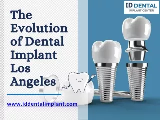
Biologic width The clinical term biologic width denotes the dimensions of periodontal and periimplant soft-tissue structures such as the gingival sulcus, the junctional epithelium, and the supracrestal connective tissues. www.rxdentistry.net
Biologic width According to measurements conducted by Gargiulo et al, the average biologic width (from the base of the sulcus to the alveolar bone margin) is 2.04 mm, of which 0.97 mm is epithelial attachment and 1.07 mm is connective tissue attachment. These dimensions, however, are in no way static but subject to interindividual variation (from tooth to tooth and from patient to patient) and will also vary according to gingival type and implant concepts. Gargiulo et al. J Periodontol.1961 Cohen DW. Biologic width. Washington,DC. Presented at Walter ReedArmy Medical Center; 1962. www.rxdentistry.net
Biologic width www.rxdentistry.net
Biologic width Numerous studies have shown that bone resorption around the implant neck does not start until the implant is uncovered and exposed to the oral cavity. This invariably leads to bacterial contamination of the gap between the implant and the superstructure. Bone remodeling will progress until the biologic width has been created and stabilized. Quirynen M, Van Steenberghe D. Clin Oral Implants Res. 1994 Quirynen et al. Clin Oral Implants Res. 1994 Ericsson et al. J Clin Periodontol. 1995 Persson et al. Clin Oral Implants Res. 1996. www.rxdentistry.net
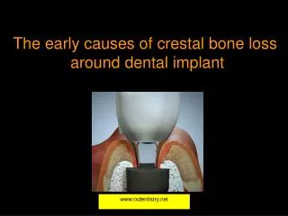
Biologic width This width progress not only apically, along the vertical axis, but according to studies conducted by Tarnow et al, there is also a horizontal component amounting to 1–1.5 mm. This is the reason to maintain a minimum distance of 3 mm between 2 implants and platform switching in the esthetic reconstruction zone in order to obtain intact papillae and stable inter-implant bone. Tarnow et al. J Periodontol. 2000 Tarnow et al.. J Periodontol. 1992 Tarnow et al. J Periodontol. 2003 www.rxdentistry.net
Biologic width www.rxdentistry.net
Biologic width This width progress not only apically, along the vertical axis, but according to studies conducted by Tarnow et al, there is also a horizontal component amounting to 1–1.5 mm. This is the reason to maintain a minimum distance of 3 mm between 2 implants and platform switching in the esthetic reconstruction zone in order to obtain intact papillae and stable inter-implant bone. www.rxdentistry.net
Summary and additional parameters on the functional and esthetic long-term results bone volume/bone quality Misch CE. Contemporary Implant Dentistry. 2nd ed. Mosby; 1999 www.rxdentistry.net
Summary and additional parameters on the functional and esthetic long-term results Mucosal quality: type/thickness Kois JC. Compend Contin Educ Dent. 2001 Kois JC. J Esthet Dent. 1994;6:3-9. www.rxdentistry.net